Capítulo 4 - MÉTODO
DE INSPEÇÃO POR CORRENTES PARASITAS
traduzido do livro: AIR
FORCE TO 33B-1-1 / ARMY TM 1-1500-335-23 / NAVY (NAVAIR) 01-1A-16-1 -
Manual Técnico - Métodos de Inspeção Não Destrutiva, Teoria Básica
- TABELAS E FÓRMULAS DO ENSAIO DE CORRENTES
PARASITAS
- Resistência
- Resistência
- Resistência
- Resistividade
- Condutividade (inverso da
resistividade)
- Indutância
- Auto Indutância
- Fator de Enchimento ("Fill Factor")
- Fator de Enchimento
- Fator de Enchimento para Bobinas Internas
- Reatância Indutiva e Reatância Capacitiva
- Impedância
- Permeabilidade
- Permeabilidade Relativa
- Profundidade de Penetração (δ)
- Frequência necessária para uma profundidade padrão
- Atraso de fase em uma
profundidade padrão
- Frequência Limite
(fg) e Lei da "Similaridade"
- Frequência Característica
- Cobertura da Sonda e Diâmetro Efetivo da
Bobina
- Cálculo da Frequência Própria da
Descontinuidade para Ajuste do Filtro
- Medição da Condutividade
8 TABELAS E FÓRMULAS DE CORRENTES PARASITAS.
Table 8-1. Aplicações Típicas do Ensaio de Correntes Parasitas
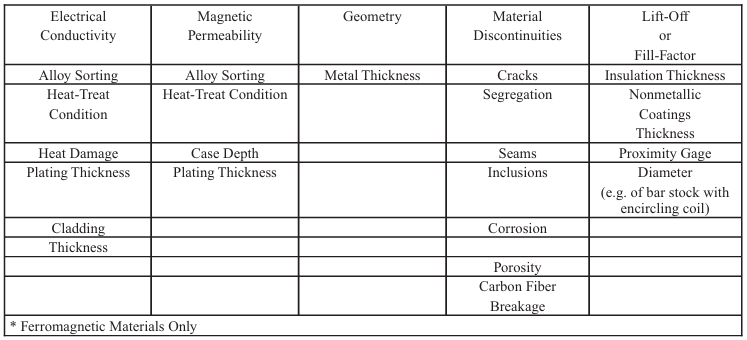
Table 8-2. Condutividade Elétrica de Alguns Materiais Comuns Utilizados
em Engenharia
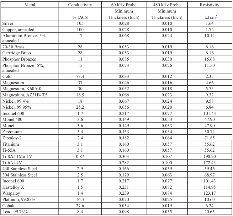
Table 8-3. Condutividade e Profundidade Padrão de Penetração Efetiva de
Vários Metais
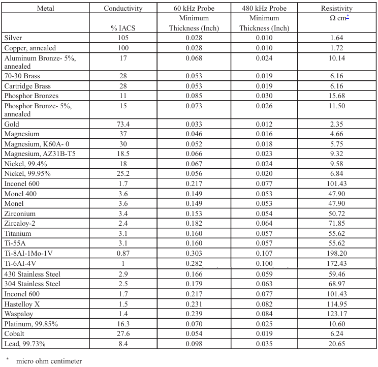
Table 8-4. Condutividade e Profundidade Padrão de Penetração Efetiva de
Ligas de Alumínio Não Revestidas
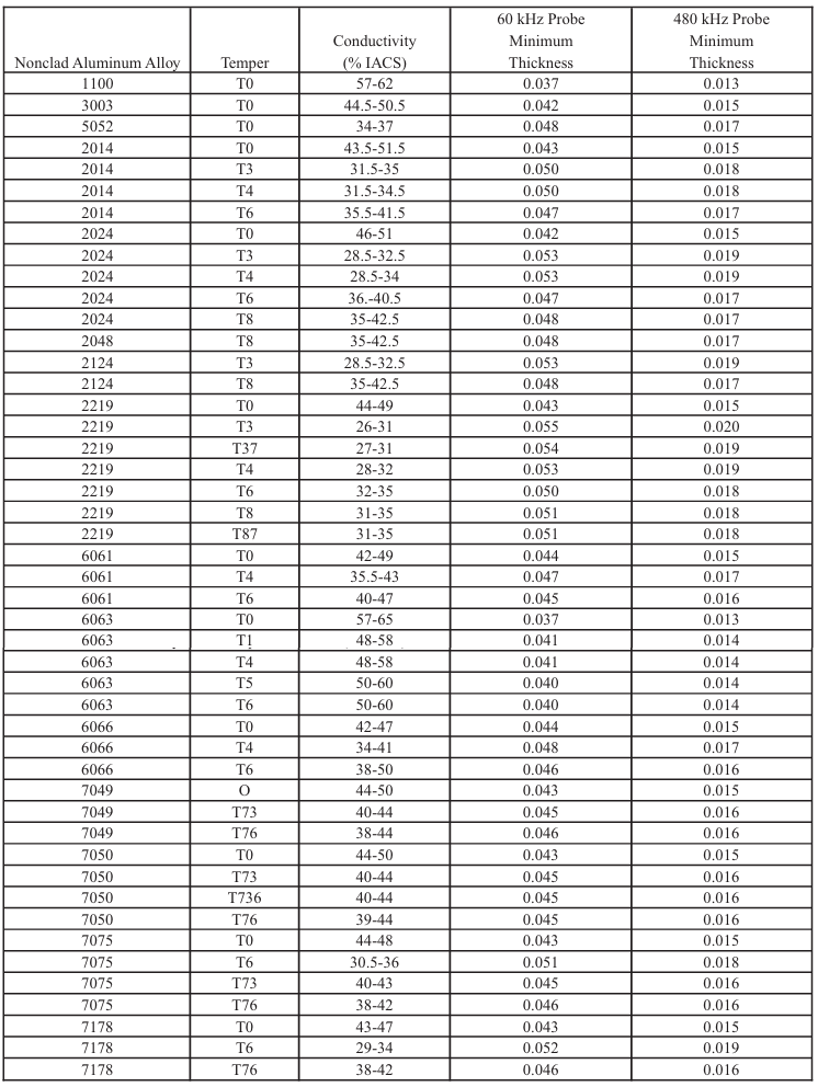
Table 8-5. Profundidade Padrão de Penetração para Ligas Metálicas a
Várias Frequências
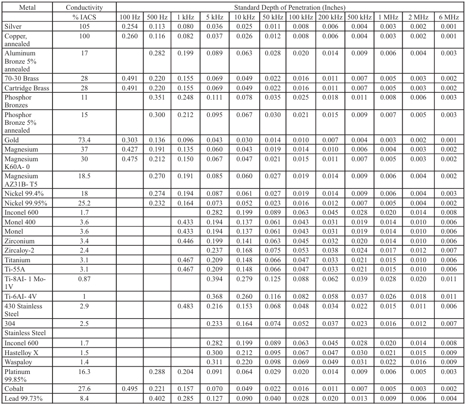
Table 8-6. Profundidade Padrão de Penetração para Ligas Revestidas de
Alumínio a Várias Frequências
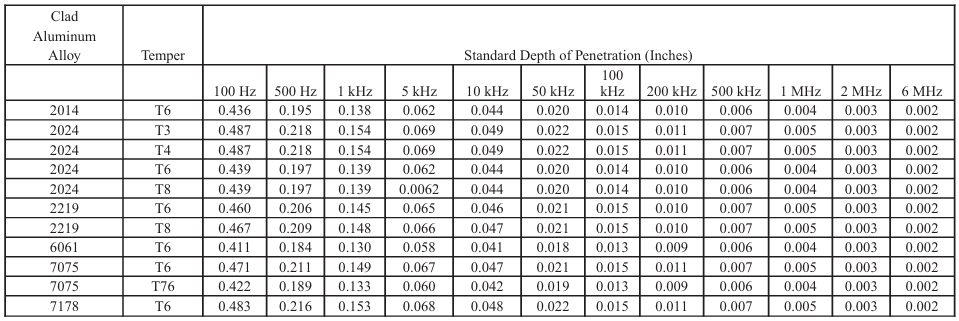
Table 8-7. Condutividade e Profundidade Padrão de Penetração Efetiva em
Ligas de Alumínio Revestidas
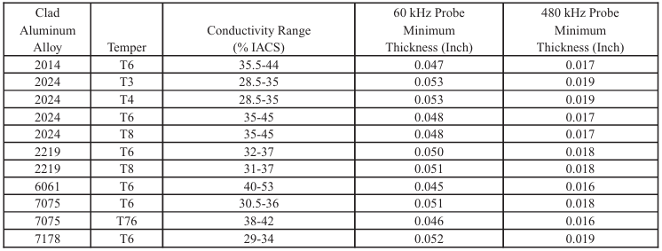
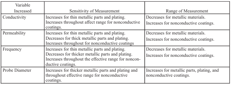
Table 8-8. Efeitos do Material e de Variáveis de Inspeção na
Sensibilidade e Faixa de Medição de Espessura
NOTA
As
fórmulas seguintes são usadas por engenheiros de END e desenvolvedores
de inspeções. Os técnicos devem ter um conhecimento da maioria dos
componentes elétricos das equações como apresentados nas aulas.
8.1 Resistência.
Quando
uma CC flue através de um elemento de um circuto, ou CA flui através de
elementos tendo uma indutância desprezivel (p.ex.: um trecho reto
de fio ou resistor de carbono), a impedância consiste apenas de
resistência elétrica e pode ser expressa como:
R = E / I
Onde:
R = Resistência (ohms)
E = Queda de Voltagem (potêncial elétrico) através do resistor (volts)
I = Corrente elétrica fluindo através do circuito (amperes)
8.1.1
Em um circuito CA contendo apenas resistência (i.e., tendo indutância
desprezível) a voltagem e corrente estão em fase (variações
concomitante no tempo). O termo em fase, quando se descreve relações
entre voltagem e corrente indica que as mudança na corrente ocorrem ao
mesmo tempo e da mesma forma (sentido) que a mudança na voltagem.
Exêmplos de duas quantidades em fase é mostrado na figura 8.1.
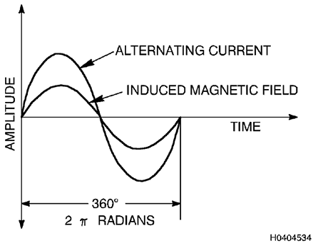
Figure 8.1. Senoides com Varação En Fae de Corrente Alternada e Campo
Magnético Induzido
8.1.2 Resistência.

Onde
l = Comprimento
do condutor
ρ= Resistividade
A = Área (seção transversal) do condutor
8.1.3 Resistividade.

8.1.4 Condutividade
(inverso da resistividade).
 mho/mm ou siemen/mm mho/mm ou siemen/mm
1 mho = 1 / ohm
8.2 Indutância.
A
indutância de uma uma sonda de correntes parasitas é resultado da
efeito no campo magnético pela corrente elétrica que circula na sonda.
A indutância é uma medida da capacidade de um circuito induzir um fluxo
de corrente em um outro circuito vizinho. Isto é proporcional a razão
entre o fluxo magnético ligado (envolvendo) um circuito e a
corrente (I) que produziu esse fluxo. Quando o fluxo de um indutor
liga-se (passa através) de outro indutor, a indutância é chamada
indutância mútua (M). Um transformador elétrico é um exemplo de um
dispositivo onde M é um parâmetro importante. Para o ensaio de
correntes parasistas, nos consideramos apenas a indutância de um
circuito de elemento simples, especificamente a bobina usada para
sentir mudanças no fluxo das correntes parasitas em uma peça ensaiada.
A indutância é chamada auto-indutância (L).0

Onde:
L = em micro-henries
r = raio médio da bobina
l = comprimento da bobina
b = espessura espiralada da bobina
N= número de voltas
8.2.1 Auto Indutância.
A
autoindutância (L) é expressa em henries. Um Henry é a indutância pela
qual um volt é produzido através de uma bobina quando a corrente
indutora é alterada à taxa de um ampere por segundo. Uma fórmula para
auto-indutância expressa nestes termos é a seguinte:

Onde:
L = Indutância (henries)
E = Força eletromotriz induzida
(volts)
I = Mudança na corrente (amperes)
T = Tempo (segundos)
Como
o henry é uma unidade grande, a indutância é mais comumente
expressa em termos de milihenries (1/1000 henry) ou micro-henries
(1/1.000.000 henry). Bobinas típicas usadas em ET têm autoindutâncias
na faixa de 10 a várias centenas de micro-henry."
8.3 Fator de Enchimento.
É
a razão entre a área da seção transversal efetiva da bobina da sonda
interna primária e a área da seção transversal do interior do tubo.

Onde:
η = Fator de enchimento
Do = Diâmetro externo da peça ensaiada
Di = Diâmetro interno da bobina
8.3.1 Fator de enchimento
Exemplo: se
uma bobina envolvente com um diâmetro interno de 2,25 polegadas fosse
usada para inspecionar uma haste de 2,00 polegadas de diâmetro, o fator
de preenchimento seria:

8.3.2
Para bobinas internas, o acoplamento eletromagnético (indutivo) é
determinado pelo entreferro entre o diâmetro externo da bobina e o
diâmetro interno que está sendo inspecionado. O fator de enchimento
é calculado usando a fórmula básica, mas neste caso Di é o diâmetro
interno da peça e Do é o diâmetro externo da bobina colocada na peça.
Por exemplo, se uma bobina com um diâmetro externo de 1,5 polegadas for
usada para inspecionar uma tubulação com um diâmetro interno de 1,6
polegadas, o fator de preenchimento é dado por:
8.4
Reatância indutiva e reatância capacitiva.
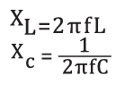
Onde:
XL = 2πfL , reatância indutiva em ohms
f = frequência em herts
L = Indutância em henrys
XC = 1 / 2πfC, reatância capacitiva em ohms
C = capacitância em faradas
8.5
Impedância.
A impedância é a oposição ao fluxo de corrente e é um
parâmetro bidimensional que consiste em resistência e reatância.
Resistência é a oposição ao fluxo de corrente contínua e alternada.
Reatância é a oposição ao fluxo de corrente alternada apenas. Reatância
pode ser capacitiva ou indutiva. Tanto a resistência quanto a reatância
são medidas em ohms. De interesse primário em CP são resistência e
reatância indutiva, esta última devido à indutância de uma bobina. A
reatância capacitiva se torna significativa em apenas alguns casos e
será discutida mais tarde. A impedância de uma bobina de teste está
relacionada ao fluxo de corrente e à queda de tensão na bobina da
seguinte forma:
Onde:
Z = Impedância da bobina (ohms)
E = Queda de tensão na bobina (volts)
I = Corrente através da bobina
(amperes)
8.5.1 Fórmula de impedância:

8.6 Permeabilidade.

Onde:
µ = permeabilidade
H = força de magnetização oersteds ou amp - espiras
B = densidade de fluxo em gauss ou tesla (10000 G = 1 T)
8.6.1
Permeabilidade Relativa:

Onde:
µo de espaço livre = 4 x 10⁻⁷
µrel ferromagnético >> 1
µrel paramagnético > 1
µrel diamagnético não ferroso < 1 Au, I
8.7 Profundidade de Penetração (δ).
 ,
resisitividade em microohms.cm ,
resisitividade em microohms.cm
 , profundidade de
penetração em mm , profundidade de
penetração em mm
 , profundidade de
penetração em polegadas , profundidade de
penetração em polegadas
 , profundidade de
penetração em polegadas usando resistividade em
microohms.cm , profundidade de
penetração em polegadas usando resistividade em
microohms.cm
8.7.1
Frequência necessária para uma profundidade padrão:
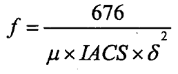 Onde:
f = frequência em hertz, Hz
µ = permeabilidade relativa
IACS =
condutividade como uma porcentagem da condutividade do cobre
δ = a
profundidade padrão de penetração em polegadas
8.7.2 Atraso de fase em uma
profundidade padrão:
 Atraso
de fase no diagrama de impedância é
2
vezes θ, sinal para baixo e para
trás com atraso de fase
1δ
é 114°
8.8 Frequência Limite, fg. e a Lei de Similaridade.


Onde:
d = diâmetro do objeto ensaiado
em cm
f = frequência I Hz
µrel = .= permeabilidade relativa
8.9
Frequência característica.
fg é a frequência mais baixa onde correntes
parasitas são induzidas em um material. Onde a frequência e a
condutividade para um material são conhecidas, a frequência para
separação de fase “similar” pode ser calculada para outro material de
condutividade conhecida.

8.10
Cobertura da bobina ou diâmetro efetivo da bobina.
Sem blindagem =
diâmetro da bobina + 4 δ
Blindagem = diâmetro da bobina
δ = Profundidade padrão de penetração
8.11
Calculando a frequência de falhas para configuração de filtros.
Suponha
que a falha seja infinitamente estreita em comparação com a bobina:
- Para varredura em uma superfície, a
velocidade da superfície é a
rapidez com que a sonda é movida sobre essa superfície
- Para uma
inspeção de furo de parafuso rotativo, a velocidade da superfície
depende da velocidade de rotação do scanner e do diâmetro da sonda. A
velocidade da superfície pode ser calculada da seguinte forma:
Frequência da Descontinuidade (Hz) =
Velocidade de Varredura (mm/s) / Diâmetro Efetivo da Sonda (mm)
Velocidade de Varredura = "SCANNER" (RPM) x 3,141592 x Diâmetro
Efetivo da Sonda
8.12 Medição de Condutividade.
Fórmula: Σ = L/RA = 1/ ; portanto, R = L/A
Onde:
Σ = condutividade elétrica (mhos/unidade de comprimento)
L = comprimento
R = resistência (ohms)
A = área da seção transversal = resistividade
(ohms-unidade de comprimento)
|