Capítulo 4 - MÉTODO
DE INSPEÇÃO POR CORRENTES PARASITAS
traduzido do livro: AIR
FORCE TO 33B-1-1 / ARMY TM 1-1500-335-23 / NAVY (NAVAIR) 01-1A-16-1 -
Manual Técnico - Métodos de Inspeção Não Destrutiva, Teoria Básica
- GERAL
- Ponto de Balanço
- Parâmetros
- Frequência
- Ganho
- Ângulo de Fase
- Sensibilidade
- Filtros
- Análise de Modulação
- Resposta de Frequência
- Inspeção de Furos de Rebites
- Trincas na Parede dos Furos de Rebites
- Trincas de Fadiga
- Trincas de Corrosão Sob Tensão
- Acabamento Superficial e Dimensões de
Furos de Rebites
- Efeito de Borda
- Preparação do Furo de Rebite
- Aparelho de Inspeção de Furos de Rebites
- Varredura Manual
- Varredura Automática
- Dispositivo de Varredura Rotativo
- Sondas para Dispositivos de Varredura
Rotativo
- Ajustagem da Sonda
- Proteção da Sonda
- Compensação de Lift-off na Inspeção de
Furos de Rebite
- Padronização de Ajustes do Aparelho
- Velocidade e Trajetória da Varredura
- Alinhamento da Sonda
- Distância Sonda-Borda
- Interpretação do Sinal de Correntes
Parasitas na Inspeção de Furos de Rebite
- Furos Ovalizados
- Furos com Rebites Não Removíveis
- Aplicação de Inspeção dos Furos
- Espaçamento da Sonda ao Furo
- Guias de Varredura ao Redor de Rebites
Não Removíveis
- Seleção da Sonda
- Padrões de Calibração para Furos com
Rebites Não Removíveis
- Filetes e Cantos Arredondados
- Bordas (Incluindo Cantos Vivos e
Arredondados)
- Ocorrência de Trincas
- Requisitos da Aparelhagem para Ocorrência
de Filetes e Cantos Redondos)
- Padrões de Referência para Filetes
- Corrosão
- Requisitos do Sistema para Detecção de
Corrosão
- Tipos de Corrosão
- Ataque Uniforme
- Pites
- Ataque intergranular
- Esfoliação
- Trincas de Corrosão Sob Tensão
- Seleção da Frequência
- Seleção da Sonda
- Padrões de Referência para Corrosão
- Prodedimento de Inspeção para Detecção da
Corrosão
- Preparação da Peça a Ser Inspecionada
- Medição da Condutividade no Campo
- Condutividade das Ligas de Alumínio
- Efeitos do Tratamento Térmico na
Condutividade do Alumínio
- Discrepâncias em Tratamentos Térmicos de
Ligas de Alumínio
- Aplicação de Medição da Condutividade
- Separação de Ligas e Revenidos
- Medição de Condutividade e Materiais
Magnéticos
- Aplicação Típica
- Controle de Tratamento Térmico
- Determinação de Danos por Calor e Fogo
- Medição da Condutividade
- Aparelho para Materiais Magnéticos
- Efeitos das Variações das Propriedades dos
Materiais
- Condutividade
- Efeito de Borda
- Curvatura
- Material do Clad
- Permeabilidade Magnética
- Geometria
- Espessura do Metal
- Efeitos das Variações das Condições de
Ensaio
- Frequência
- Sondas para Medição da Condutividade
- Efeito Lift-off na Medição da
Condutividade
- Efeito da Temperatura nas Medições de
Condutividade
- Detecção de Descontinuidades
- Capacidade do Sistema de Ensaio
- Seleção da Sonda
- Tipos de Sonda
- Material
- Acessibilidade
- Requisitos de Frequência
- Relação Sinal-Ruído
- Relação Sinal-Ruído e Detectabilidade
- Influência da Frequência no Ruído
- Técnicas de Supressão
- Solucionando Energia
- Efeitos de Lift-off
- Fontes de Variação de Lift-off
- Supressão do Lift-off
- Métodos de Compensação de Lift-off
- Aparelhos de Análise no Plano de
Impedâncias
- Ajuste de Fase
- Efeito de Lift-off na Detectabilidade
- Compensação do Efeito de Lift-off na
Detectabilidade
- Defasagem Devido a Trincas
- Materiais Ferromagnéticos
- Descriminação de Fase
- Oscilação/Vibração da Sonda
- Efeitos da Localização da Trinca na
Detectabilidade
- Localização e Orientação das Trincas
- Trincas na Borda da Peça
- Inspeção das Bordas da Peça
- Dispositivos de Fixação e Suporte para
Inspeção de Bordas
- Curvatura
- Detecção de Descontinuidades Sub
superficiais
- Análise no Plano de Impedão de Trincas
Sub superficiais
- Detecção de Trincas Sob Revestimentos
Metálicos
- Efeitos do Método de Varredura na
Detectabilidade
- Técnica de Inspeção
- Velocidade de Varredura
- Trajetória da Varredura
- Aparelhos Automáticos ou Semi Automáticos
- Uso de Registradores ou Telas Digitais
- Padrões de Referência de Trincas
- Trincas Empregadas em Padrões de
Referência
- Requisitos dos Padrões de Referência
- Padrões para Ensaios Específicos
- Descontinuidades Artificiais para Padrões
- Condições Simuladas para Padrões
- Entalhes Usinados por Eletroerosão
- Entalhes por Eletroerosão em Aços
Ferromagnéticos
- Entalhes por Corte
- Entalhes Usinados
- Escolha do Padrão de Referência para
Trincas
- Medição de Espessura
- Critérios de Aplicação
- Tipos de Medição
- Tipos de Medição (Continuação)
- Limitações Gerais da Medição de Espessura
de Chapas
- Sistemas de Ensaio
- Procedimentos de Medição de Espessura
- Medição da Espessura Metálica Total
- Aplicações da Medição da Espessura Total
- Limitações da Espessura Total
- Efeitos da Frequência na Medição da
Espessura Total
- Efeitos da Construção da Sonda
- Procedimento Operacional para Medição da
Espessura Total
- Preparo da Peça para Medição de Espessura
- Presença de Limitações Geométricas
- Seleção do Sistema de Ensaio
- Seleção da Frequência para Medição de
Espessura
- Ajustes do Aparelho
- Registro de Espessuras e Relatório de
Valores Rejeitados
- Padrões para Medição de Espessura Total
- Aplicações de Medição de Revestimentos
Condutores
- Aplicação Medição de Revestimentos
Condutores
- Efeitos das Propriedades do Material na
Medição da Espessura de Chapas
- Efeitos da Condição de Ensaio na Medição
da Espessura de Chapas
- Procedimentos para Medição da Espessura
de Chapas
- Padrões de Referencia de Espessura de
Chapas
- Medição de Revestimentos Não Condutores
- Revestimentos Não Condutores
- Base para Medição de Revestimentos Não
Condutores
- Efeitos na Impedância de Revestimentos
Não Condutores
- Influência das Propriedades dos
Materiais e da Frequência
- Sistemas de Ensaio de Revestimentos Não
Condutores
- Procedimentos para Medição de
Revestimentos Não Condutores
- Padrões para Medição de Revestimentos Não
Condutores
5 GERAL.
Todas
as inspeções para detecção de trincas ou outras falhas em serviço DEVEM ser
consideradas críticas. Cada inspeção em cada aeronave ou sistema de
armas deve ser abordada com o máximo cuidado e concentração. Sempre
configure seu instrumento de correntes parasitas de acordo com os
procedimentos estabelecidos. Certifique-se de verificar sua
configuração várias vezes durante a inspeção para garantir que seu
equipamento esteja respondendo corretamente. Reserve um tempo para
garantir que você tenha escaneado cuidadosamente toda a área de
inspeção, verificando suas varreduras duas vezes, se necessário. A
inspeção que você realiza pode ser a última linha de defesa contra uma
possível falha devido ao crescimento de fissuras. Não encontrar um
defeito em uma área durante uma inspeção anterior não diminui as
chances de ele se apresentar no futuro. Aborde cada inspeção como se
houvesse uma falha conhecida na área que você está inspecionando.
5.1
Ponto Nulo (de balanço ou de trabalho).
O ponto nulo é o local em um plano de impedância no qual o
instrumento de correntes parasitas é anulado ou zerado. Se anulado
corretamente em um material sem defeitos, o instrumento posicionará o
sinal (ponto) em um ponto específico da tela, e quaisquer alterações no
material, como uma trinca, farão com que o sinal (ponto) reflita uma
alteração na impedância elétrica no visor/tela.
5.2
Parâmetros. Há um grande número de parâmetros que podem ser definidos
em um instrumento de correntes parasitas. No entanto, os parâmetros
mais frequentemente ajustados pelos técnicos são frequência, ganho,
ângulo de fase, ponto de trabalho, escala da tela e filtros.
5.2.1 Frequência.
O
único parâmetro livremente ajustável em instrumentos modernos que afeta
as correntes parasitas é a frequência. Os demais parâmetros existem
apenas para melhorar a visibilidade da resposta do sinal no
instrumento. Quanto menor a frequência, mais profundo o campo penetra
no material e, portanto, maior a profundidade na qual as correntes
parasitas fluem. No entanto, o campo não apenas se aprofunda, mas
também se espalha, ou seja, se dilui, resultando em menor sensibilidade
a pequenas variações (ver Figura 5.1). (N.T.: O uso de menor frequência
de ensaio implica em menor geração de correntes parasitas desde a
superfície na qual está a sonda.).
A propagação das correntes parasitas depende da condutividade do material e da frequência de acionamento do instrumento
5.2.1.1
A frequência não afeta a intensidade das correntes parasitas,
apenas a dispersão. (N.T.: Considerando o fenômeno de indução
eletromagnética essa afirmação não é valida). Alguns instrumentos podem
permitir o ajuste da
tensão de acionamento que passa pela bobina geradora, o que, por sua
vez, afeta a intensidade das correntes parasitas, resultando em maior
sensibilidade na detecção de falhas. Isso é independente do ajuste de
frequência.
5.2.2 Ganho.
O
ganho pode ser aumentado para obter uma resposta de sinal maior (ou
seja, para tornar um sinal pequeno mais visível) ou diminuído para
reduzir a resposta do sinal no visor do instrumento. No entanto,
aumentos no ganho aumentarão o "ruído" no visor do instrumento. O ruído
pode ser causado por diversos fatores: a eletrônica do instrumento (não
tão comum em instrumentos modernos), ruído do material resultante da
estrutura de grãos do material, ruído do material causado pela
alteração mecânica da superfície do material ensaiado, etc.
5.2.2.1
Alguns instrumentos possuem ganho H (dispersão X) ou ganho V (dispersão
Y) além do ganho regular. Esses dois ganhos permitem que o operador
aumente ou diminua o sinal independentemente na direção vertical ou
horizontal e são muito úteis para ajudar a distinguir sinais de ruído
de respostas defeituosas.
5.2.3 Ângulo de Fase.
Também
conhecido como rotação ou ângulo de rotação. Independente da fase real
das correntes parasitas, é uma configuração que permite ao usuário
rotacionar as respostas do sinal na tela do instrumento. Pode ser usado
para orientar a resposta do sinal ao levantar a sonda do material
(sinal de lift-off, ao usar uma sonda absoluta). Isso ajuda o usuário
a distinguir entre lift-off e um sinal provavelmente causado por uma
falha.
5.2.4 Sensibilidade/Detectabilidade.(não
disponível em todos os instrumentos)
Parâmetro que permite a ampliação
do visor do instrumento. Atua como o recurso de "zoom" da câmera; não
melhora a imagem, apenas a torna maior ou menor. É usado para definir a
escala do reticulado exibida na tela. Uma configuração comum é 1 Volt por
divisão de escala. Isso significa que um sinal com 2 divisões de escala
tem uma tensão de 2 Volts. Essa medida é usada para classificar sinais
como aceitáveis ou rejeitáveis.
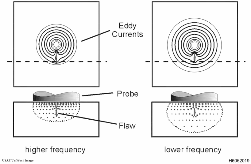
Figura 5.1. Ilustração da distribuição das correntes parasitas com a frequência
5.2.5 Filtros.
Usados
para filtrar sinais indesejados e melhorar a relação sinal-ruído,
conforme ilustrado na Figura 5.2. Três tipos de filtros podem ser
usados: passa-alta, passa-baixa e passa-faixa. Um filtro passa-alta
(HPF) remove sinais de baixa frequência e permite a passagem de altas
frequências, sendo útil para eliminar o efeito de variações graduais na
condutividade ou dimensões na resposta de correntes parasitas. Um
filtro passa-baixa (LPF) remove sinais de alta frequência e permite a
passagem de sinais de baixa frequência, sendo útil para reduzir os
efeitos do ruído eletrônico e da resposta de alta frequência de
frequências harmônicas relacionadas a variações na permeabilidade
magnética. Os filtros passa-faixa combinam filtros passa-baixa e
passa-alta para permitir uma resposta em uma faixa específica de
frequências e suprimir frequências acima e abaixo dessa faixa.
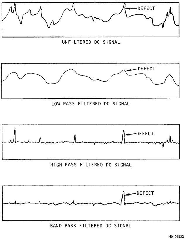
Figura 5.2. Ilustração dos efeitos de diferentes filtros no sinal de correntes parasitas.
- 5.3 Análise de modulação.
- Uma
técnica útil para separar sinais de interesse de outros sinais
baseia-se na análise dos sinais em função do tempo. Um bom exemplo
disso é o uso de um registro gráfico X e/ou Y (gráfico de faixas), onde a
amplitude do sinal aparece na escala vertical e os tempos em que o
sinal aparece e desaparece são monitorados na horizontal.
5.3.1
Um exemplo de análise de modulação é quando uma tela de instrumento de
plano de impedância é usado no modo de varredura durante uma inspeção
rotativa de furo de parafuso. Nessa técnica, o equipamento é
tipicamente configurado de forma que cada traço ao longo da varredura
represente uma rotação no furo. A posição do relógio de uma indicação
no furo pode ser determinada por sua localização ao longo da varredura.
De maior importância é a largura da indicação ou por quanto tempo ela
se desvia da linha de base. Neste exemplo, o tempo durante o qual a
indicação é detectada (largura) é usado para identificar se ela se deve
ou não a uma variável de interesse. Por exemplo, uma irregularidade em
um furo de parafuso produzirá uma indicação que dura um longo período,
enquanto uma trinca é muito estreita e produz uma indicação que dura um
curto período. Ambas as indicações podem ter a mesma amplitude, mas
talvez apenas a trinca seja de interesse. Um filtro eletrônico pode ser
usado para suprimir sinais de longa duração (baixa frequência),
deixando apenas a indicação de trinca (alta frequência) no visor para o
inspetor visualizar.
- Em
relação à análise de modulação, é importante entender que os termos
alta e baixa frequência se referem à duração da indicação, não à
frequência da corrente alternada na bobina.
5.3.2
A frequência de uma indicação é o recíproco do seu período de duração,
ou seja, quantos eventos (ciclos) desse tipo poderiam ocorrer em 1
segundo. Por exemplo, suponha que a indicação do furo fora de
circularidade discutida no Parágrafo 5.3.1 dure 0,1 segundo ao longo
da varredura, e a indicação da trinca dure 0,01 segundo ao longo da
varredura. A frequência f do sinal fora de circularidade seria 1/0,1 ou
10 ciclos/seg (Hz), e a da trinca seria 1/0,01 ou 100 ciclos/seg (Hz).
Um filtro passa-alta poderia ser ajustado em 50 Hz para suprimir sinais
abaixo de 50 Hz e permitir a exibição de sinais acima de 50 Hz. Como
também pode haver sinais com frequência mais alta do que a variável de
interesse, um filtro passa-baixa também pode ser usado para suprimir
ruído de alta frequência. Este filtro pode ser definido em 200 Hz para
o exemplo acima. Usados em conjunto, os filtros passa-alta e
passa-baixa formam o que é chamado de filtro passa-banda, o que
significa que apenas sinais com frequência acima de uma faixa
específica são exibidos. No exemplo acima, sinais acima de 200 Hz são
suprimidos pelo filtro passa-baixa, e sinais abaixo de 50 Hz são
suprimidos pelo filtro passa-alta. Para passar por ambos os filtros, o
sinal deve estar entre 50 e 200 Hz, ou durar de 0,005 a 0,02 segundos.
5.4
Resposta em Frequência.
A análise de resposta em frequência é a forma
mais comum de análise de modulação. Durante o ensaio de correntes
parasitas, a impedância da bobina de ensaio permanece constante, desde
que não haja alteração nas condições de inspeção ou nas propriedades do
material. Quando ocorrem variações na impedância, as taxas de variação
na impedância e o sinal de corrente parasita resultante são
proporcionais às taxas de variação das propriedades do material e à
velocidade de varredura. Consequentemente, uma pequena fissura
proporcionaria uma rápida variação na impedância durante a varredura e
um sinal de corrente parasita de alta frequência correspondente. Esses
sinais podem ser visualizados em um monitor de vídeo ou em um
registrador gráfico de sinais em função do tempo. O efeito na
amplitude, ao encontrar diferentes tipos de variações do material e ao
varrer a uma velocidade constante, é mostrado na Figura 5.3. Uma
rápida mudança de sinal costuma ser um bom indicador de uma pequena
falha ou de uma mudança abrupta nas características do material. Uma
lenta mudança de sinal geralmente indica uma mudança gradual nas
dimensões, elevação ou alguma outra propriedade.
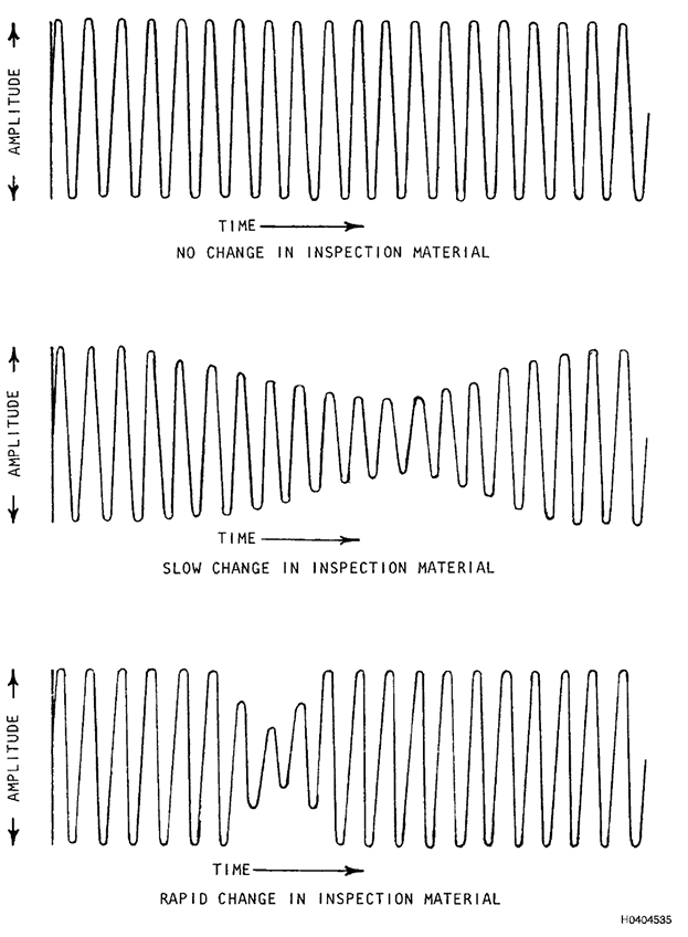
Figura 5.3. Efeito de variáveis materiais na magnitude da corrente alternada na bobina de ensaio com velocidade de varredura constante
5.5 Inspeção de furos de fixação.
5.5.1
Trincas em Paredes de Furos de Fixadores. Uma aplicação comum da
inspeção por correntes parasitas em estruturas de aeronaves é a
detecção de trincas em furos ou paredes de fixadores. Essas trincas são
geralmente geradas por fadiga, corrosão sob tensão ou uma combinação de
fadiga e corrosão. O progresso dessas trincas costuma ser lento no
estágio inicial, onde a detecção precoce pode prevenir possíveis falhas
catastróficas.
5.5.1.1 Trincas por Fadiga.
As
trincas por fadiga são geralmente causadas por carregamentos cíclicos
repetidos sobre uma estrutura, com níveis de tensão inferiores aos
necessários para a deformação visível. Como a tensão se concentra em
áreas de fragilidade localizada, como furos, as trincas por fadiga
frequentemente se iniciam nesses pontos. As trincas geralmente se
propagam normal à direção da tensão máxima de tração aplicada. A
seguir, descrevemos dois tipos de fadiga:
- Fadiga
de Alto Ciclo (FAC). FAC geralmente significa que a tensão aplicada é
baixa em comparação com a resistência à tração final do material, mas
submetida a um número muito alto de ciclos (exemplos: tensões de
vibração ou turbulência do ar).
- Fadiga
de Baixo Ciclo (LCF). LCF geralmente significa que a tensão aplicada é
alta em comparação com a resistência à tração final do material, mas
submetida a um número muito baixo de ciclos (exemplos: tensões de
decolagem e pouso).
5.5.1.2 Trincas por Corrosão sob Tensão.
Trincas
por corrosão sob tensão ocorrem sob a influência combinada de uma
tensão de tração e de um ambiente corrosivo sobre um material
suscetível à corrosão sob tensão. A tensão de tração pode resultar de
uma tensão aplicada ou de uma tensão residual. A umidade do ar
combinada com um ambiente suficientemente corrosivo pode, em alguns
casos, causar trincas por corrosão sob tensão. Além disso, a combinação
de fadiga cíclica na presença de trincas por corrosão pode causar o
rápido crescimento das trincas.
5.5.1.3 Acabamento e Dimensões da Parede do Furo.
O
acabamento e as dimensões da parede do furo influenciam tanto a
ocorrência quanto a detectabilidade de trincas em furos de fixadores.
Danos na parede do furo, como arranhões, trepidações e ranhuras criadas
durante a fabricação, podem criar concentrações adicionais de tensão na
parede do furo e fornecer locais preferenciais para o início de
trincas. Parafusos frouxos causados por furos superdimensionados ou
fora de circularidade permitem movimento na área do furo e permitem
ação de fadiga. Essas mesmas condições podem influenciar a
confiabilidade da inspeção. Durante a inspeção, danos severos à parede
do furo resultam em indicações de correntes parasitas que podem não ser
separáveis das indicações de trincas. O lift-off excessivo devido
a condições fora de circularidade também pode mascarar indicações de
trincas. Todas essas condições podem ser criadas durante os processos
de fabricação no furo ou como resultado da ação de fadiga durante o
serviço e da remoção do parafuso.
5.5.1.4
Efeitos de Borda. Muitas trincas em furos de fixadores ocorrem na borda
do furo ou próximo a ela. Estruturas adjacentes, raios de escareamento
e rebarbação não uniformes e danos nas bordas do furo aumentam o ruído
de fundo e diminuem a relação sinal-ruído. Isso leva a uma perda geral
de detecção de trincas na borda dos furos. Outros efeitos na
detectabilidade de trincas resultam da presença de outros metais
adjacentes à borda do furo. Superfícies escareadas também limitam a CP
por técnicas manuais adjacentes às bordas do furo.
5.5.2
Preparação dos Furos dos Parafusos. Os furos nas superfícies de contato
devem ser realinhados antes da inspeção CP ou perfurados com um
diâmetro maior, que seja concêntrico através das peças de contato.
Antes de realizar a inspeção dos furos dos parafusos, todo o material
estranho deve ser removido do furo. Materiais estranhos podem incluir
selantes, lubrificantes, lascas de metal e lascas de tinta.
Normalmente, esse material pode ser removido com cotonetes e um
solvente adequado. Furos severamente danificados durante o serviço ou
durante a inserção/remoção de fixadores podem exigir alargamento antes
da inspeção CP. Se alargamento for necessário, entre em contato com o
engenheiro responsável pelo componente para obter um método aprovado.
5.6 Aparelho de inspeção de furos de fixadores
CUIDADO
Em
geral, a capacidade de detecção da varredura manual de furos de
parafusos é significativamente menor do que a varredura automática de
furos de parafusos e, portanto, NÃO DEVE substituír a varredura
automática, a menos que especificado em procedimentos específicos da
peça ou em autorização específica por escrito da autoridade de
engenharia responsável.
5.6.1 Escaneamento manual de furos de parafusos.
CUIDADO
A
inspeção automática por correntes parasitas em furos de parafusos
(BHEC-Bolt Hole Eddy Current) DEVE ser realizada de acordo com a Ordem Técnica (TO=Technical Oredere) do sistema de armas
aplicável e/ou o pacote de trabalho apropriado na TO 33B-1-2 para o
procedimento específico a ser executado. Salvo indicação em contrário,
a TO específica do sistema de armas sempre tem precedência sobre as
recomendações do fabricante ou qualquer TO geral.
Quando
utilizada, a varredura manual dos furos de parafusos é realizada em
níveis especificados em toda a profundidade do furo. A inspeção
geralmente é iniciada com o centro da bobina da sonda posicionado
imediatamente dentro da borda superior ou inferior do furo, de modo que
a borda externa da bobina fique nivelada com a superfície da peça. A
posição da bobina da sonda é ajustada para o nível especificado abaixo
do colar da sonda, e a sonda é inserida no furo até que o colar da
sonda encoste na superfície da peça. Ocasionalmente, a corrosão sob
tensão intergranular (IGC) pode ocorrer ao longo de um plano
aproximadamente paralelo à superfície da peça. A indicação desse tipo
de corrosão é semelhante a um furo de formato elíptico ou a uma mudança
lenta na condutividade. A aplicação incorreta da filtragem passa-faixa
pode mascarar a presença de IGC.
5.6.2
Varredura Automatizada de Furos de Parafuso.
A varredura automática é
normalmente usada para inspeção de furos de parafuso devido à maior
capacidade de detecção em relação à varredura manual. Este equipamento
fornece uma unidade de varredura portátil que aciona uma sonda propciando uma varredura em um
padrão helicoidal ao longo do furo, ou gira a sonda em altas revoluções
por minuto, a uma velocidade constante enquanto o operador indexa/movimenta a
sonda através do comprimento do furo. O equipamento que gira a sonda em um padrão
helicoidal é chamado de dispositivo de varredura ("scanner") de rotação translacional. Muitas vezes,
"scanners" de alta velocidade não têm movimento translacional
automatizado e dependem da velocidade na qual o operador empurra e puxa a
sonda para dentro e para fora do furo. Os resultados podem ser
armazenados em um registrador de gráfico de tiras ou exibidos em um
visor digital.
5.6.2.1
O "Scanner" Rotativo.
O "scanner" gira a sonda do furo de parafuso a uma
determinada velocidade, que foi definida no instrumento durante a
configuração. A sonda deve ser inserida no furo do fixador e
movimentada no furo a uma velocidade lenta o suficiente para que a
bobina na sonda
escaneie toda a superfície da parede do furo em uma espiral fechada,
garantindo assim 100% de cobertura da superfície (veja a Figura 5.4).
5.6.3
Sondas Rotativas para Furo de Parafuso.
O projeto mais comum de sonda
para furo de parafuso é mostrado na Figura 5.4. A sonda consiste em
uma carcaça com um conector de 4 pinos e um corpo principal. A carcaça
possui dois anéis de vedação que prendem e centralizam a sonda no
receptáculo do conector do "scanner". Itens fornecidos pelo fabricante
como parte integrante da construção ou operação da sonda, como anéis de
vedação, NÃO DEVEM ser removidos. O corpo consiste em uma haste com uma
esfera integrada na extremidade, chamada de "cabeça". A haste é
bipartida e uma das duas metades da cabeça contém a bobina do sensor. A
cabeça bipartida proporciona flexibilidade de mola para garantir que a
bobina do sensor possa ficar o mais próximo possível da parede do furo
do fixador. Ao escolher uma sonda para furo de parafuso, o diâmetro da
esfera deve ser igual ou ligeiramente menor que o do furo do fixador a
ser inspecionado. Isso proporciona o melhor ajuste após a haste ser
aberta e a fita aplicada.
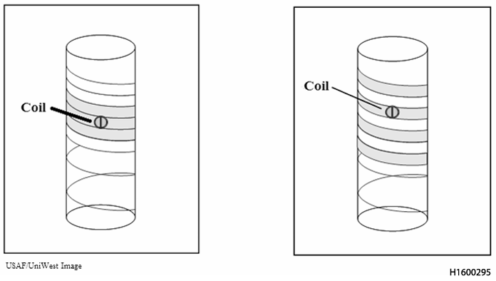
Figure 5.4. Técnica adequada para garantir 100% de cobertura (esquerda), cobertura incompleta (direita)
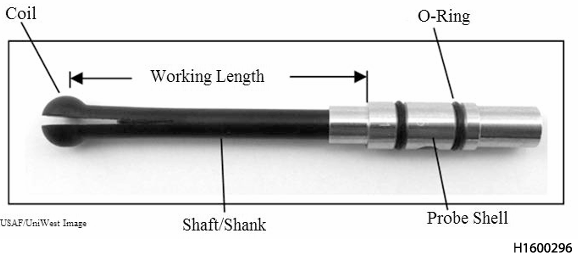
Figure 5.5. Projeto Típico de Sonda para Furo de Fixador
5.6.3.1
Há uma variedade de outros projetos, como sondas com cabeças cônicas ou
cilíndricas, ou sem cabeça alguma. No entanto, estudos demonstraram que
a sonda em formato de esfera fornece ótima detectabilidade de falhas em
todo o furo de um fixador, incluindo na borda de ambas as extremidades
abertas. O formato de esfera ajuda a garantir que a bobina esteja em
contato com a parede do fixador, mesmo que a sonda não esteja
totalmente alinhada com o eixo do furo.
5.6.3.2
A Figura 5.6 mostra a configuração típica da bobina em uma sonda para
furo de parafuso. A bobina consiste em duas bobinas receptoras, cada
uma enrolada em uma ferrite em formato de D. As bobinas receptoras são
então colocadas lado a lado e uma bobina condutora é enrolada em torno
de ambas. Os receptores são conectados de forma diferente (polos elétricos). Isto
significa que se a Bobina Receptora 1 "vê algo", ela causa uma resposta
de sinal ascendente. Se a Bobina Receptora 2 vê algo, ela causa uma
resposta de sinal descendente. Este tipo de bobina é chamado de
reflexão diferencial
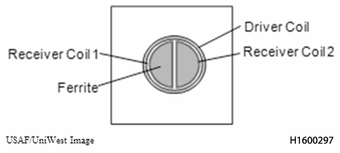
Figura 5.6. Configuração da Bobina em uma Sonda de Furo de Parafuso
5.6.3.3
A Figura 5.7 (A) mostra uma sonda de furo de parafuso típica com uma
bobina de reflexão diferencial padrão "D50". A bobina excitadora ("driver") é a bobina
mais externa. A bobina "driver" gera um campo magnético alternado que
penetra no material condutor. O material reage gerando correntes
parasitas cujo campo se opõe ao campo eletromagnético primário. Como o
campo magnético de entrada é espalhado, ou seja, o campo efetivo tem
uma área efetiva muito maior do que apenas o diâmetro da bobina, as
correntes parasitas são assim mais espalhadas.
5.6.3.4
A Figura 5.7 (B) mostra a distribuição de correntes parasitas para a
sonda mostrada na Figura 5.7 (A). As correntes parasitas fluem no
mesmo padrão circular que os enrolamentos da bobina condutora, são mais
fortes perto dos enrolamentos da bobina e dissipam-se lentamente no
material condutor. A figura mostra a extensão e a profundidade externas
das correntes até o ponto em que sua intensidade atinge 37% da
intensidade na superfície (profundidade de penetração padrão). Neste
exemplo, o resultado é que, em um componente de alumínio a 200 kHz, uma
sonda com uma bobina condutora de 0,070" de diâmetro gerará um campo de
correntes parasitas com cerca de 0,008" de profundidade no material e
terá uma área de detecção que se estende por aproximadamente 0,086" de
diâmetro.
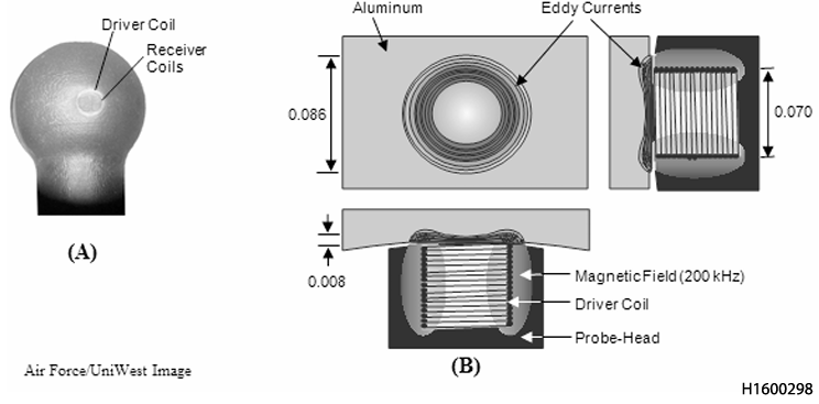
Figure 5.7. Exemplo de (A) Sonda de Furo de Parafuso e (B) Bobina de Excitação e Geração de Correntes Parasitas
.
5.7
Ajuste da Sonda.
Uma sonda que se encaixe corretamente dentro do furo
é essencial para o desempenho da inspeção. Uma sonda mal ajustada
vibrará no furo, resultando em elevação excessiva e ruído de sinal.
CUIDADO
Somente
sondas do tamanho correto DEVEM ser usadas para realizar a inspeção de
furos de parafusos por correntes parasitas. A inspeção com uma sonda
mal ajustada pode resultar em indicações de trincas perdidas.
5.7.1 A seguir apresenta-se uma sequência simples para garantir um bom encaixe da sonda:
- a. Meça o diâmetro do furo do parafuso se você não o souber;
- b. Selecione uma sonda com uma faixa de tamanho que se ajuste ao furo do parafuso;
- c. Aplique a sonda com fita adesiva; não a insira no scanner;
- d. Insira-a no furo;
- e.
Se a sonda puder quase ficar em pé no furo (se o furo for vertical e
para baixo), ou ficar pendurada dentro do furo (se o furo for vertical
e para cima), ou não escorregar para fora do furo (se o furo for
horizontal) e se você ainda puder girá-la suavemente com a mão, o
encaixe da sonda está correto (Figura 5.8)
- f.
Se o encaixe não estiver correto, coloque um pouco de espuma não
condutora ou material emborrachado na fenda da haste da sonda e tente
novamente.
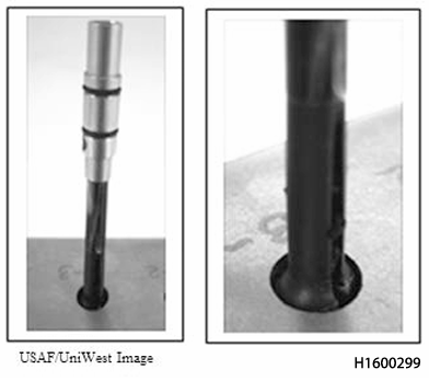
Figura 5.8. Verificando o ajuste da sonda no furo
5.8
Aplicação de Fita na Sonda.
As sondas para furos de parafusos são
fabricadas com diversos tipos de materiais, dependendo do tipo e do
fabricante da sonda. Algumas sondas são mais duráveis do que outras.
Sondas feitas de plástico macio podem se desgastar e expor os
enrolamentos da bobina em apenas alguns usos, portanto, é sempre
aconselhável carregar uma sonda extra. Uma maneira de proteger a bobina
é usar fita de "teflon" para cobri-la. Parte da duração de uma sonda e
das respostas que você observa durante uma inspeção depende da forma
como você a aplica. Deve ser usada fita com espessura entre 2,5 e 3,5
mils (0,0025-0,0035 polegadas), levemente elástica e com revestimento
adesivo. A maneira correta de aplicar a fita é enrolá-la completamente
ao redor da metade da bobina de uma sonda bipartida. As extremidades da
fita devem ser dobradas entre a sonda bipartida. A sonda bipartida
proporciona uma ação semelhante a uma mola para garantir que a bobina
mantenha contato com a superfície do furo durante a rotação. Portanto,
a fita NÃO DEVE ser enrolada completamente em torno de ambas as metades
da divisão, pois isso impedirá que a sonda se ajuste ao furo. A Figura
5.9 mostra um exemplo de uma sonda com fita aceitável. Neste exemplo,
a fita cobre suavemente a metade da bobina da sonda sem rugas e as
extremidades da fita são dobradas entre a divisão. A Figura 5.10 e a
Figura 5.11 mostram exemplos de aplicação de fita inaceitável. A Figura
5.10 mostra a fita cobrindo apenas metade da bobina, o que permitiria
que as bordas da fita subissem durante a rotação da sonda no furo, e a
Figura 5.11 mostra a fita que não foi aplicada suavemente e está
enrugada.
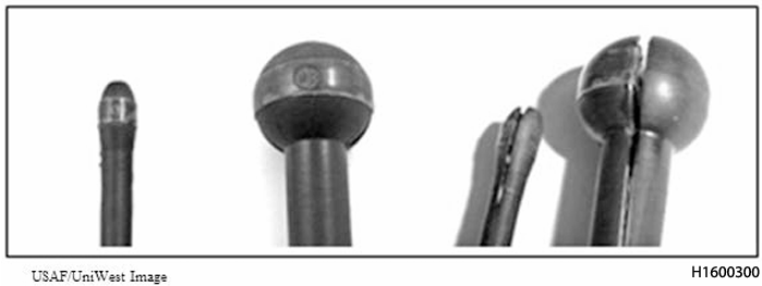
Figura 5.9. Exemplos de Sondas de Furo de Parafuso Com Aplicação Aceitavel da Fita
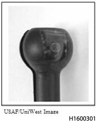
Figura 5.10. Aplicação de Fita Inaceitável (Incompleta)
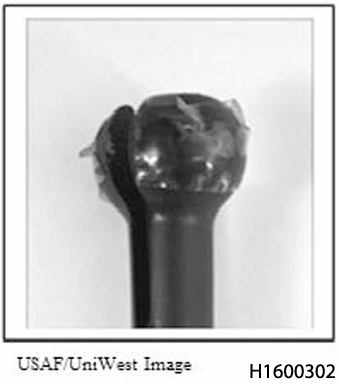
Figura 5.11. Aplicação de Fita Inaceitável (Enrugada)
5.9
Compensação de Lift-off (afstamento sonda-peça) para Inspeção de Furo de Parafuso.
A
compensação de levantamento para inspeção de furo de parafuso depende
da qualidade da superfície e das dimensões do furo. A compensação de
lift-off ideal é aquela que apenas suprime as variações de lift-off
dentro do furo, mas não fornece compensação excessiva. A compensação
excessiva de lift-off pode reduzir a sensibilidade e aumentar o ruído.
Ao usar sondas sem blindagem, quantidades específicas de compensação de
lift-off podem ser obtidas usando um calço entre a bobina da sonda do
furo do parafuso e a parede do furo. A espessura do calço deve ser
igual à quantidade de compensação de lift-off desejada e deve ser
relativamente resistente para evitar rasgos durante a inserção e
remoção da sonda. Fita de Teflon DEVE ser usada para essa finalidade. A
compensação de lift-off geralmente é realizada no furo em um ponto
afastado da borda ou no centro se a espessura da peça for inferior a
1,25 cm. Mais tolerância nas configurações de compensação de lift-off é
permitida ao usar equipamento de varredura automática ou sondas
blindadas.
5.10
Configurações do Aparelho ("Calibração").
As configurações de ajuste do
instrumento antes da inspeção são baseadas na resposta a um padrão de
referência especificado. Uma ampla variedade de padrões de ensaio é
utilizada para inspeção de furos de parafusos. Eles incluem peças
trincadas, entalhes usinados por eletroerosão (EDM), entalhes cortados
com serra de joalheiro, diferenças na condutividade dos padrões de e uma
infinidade de outros padrões com entalhes e/ou trincas maiores. Cada
procedimento individual DEVE especificar o padrão a ser utilizado e a
resposta necessária em termos de deflexão do medidor ou tamanho da
indicação em um registrador, registro gráfico ou visor do instrumento.
Quando for necessário encontrar pequenas falhas e existir a
possibilidade de diferentes tipos de sondas (tamanho da bobina e
frequência) serem utilizados, é necessário utilizar uma referência com
as mesmas dimensões aproximadas das falhas a serem detectadas, como
entalhes por eletroerosão.
5.11
Velocidade e a Trajetória de Varredura.
A velocidade e a trajetória da varredura
devem ser considerados durante a configuração do procedimento. Isso é
especialmente importante com a varredura manual, pois a resposta da
sonda com a varredura manual não será a mesma que durante a varredura
automatizada. A distância entre as varreduras ou o incremento de
varredura é determinado pelo tamanho mínimo de trinca necessário para
ser detectado. Durante a varredura manual, o procedimento de varredura
é repetido após a colocação da bobina da sonda em cada posição de
varredura até que todo o comprimento do furo tenha sido inspecionado.
Ao inspecionar múltiplas camadas, a inspeção deve ser realizada nos
materiais de cada camada adjacente a cada interface. Quando a posição
específica da interface entre camadas de material similar não for
conhecida, sua posição pode ser estabelecida passando a sonda pela
interface e marcando a posição de deflexão máxima do sinal. A
configuração e a inspeção DEVEM ser realizadas usando a mesma
velocidade e padrão de varredura para garantir a melhor resposta do
sinal e a máxima cobertura da varredura.
Ao inspecionar um furo, a sonda deve ser guiada
para dentro do furo de forma que o eixo da sonda esteja alinhado com o
eixo do furo (consulte as Figuras 5.12 e 5.13). Isso pode ser difícil
de fazer, especialmente ao monitorar a tela do instrumento ao mesmo
tempo. Se a sonda não estiver alinhada corretamente, a bobina pode não
tocar a superfície do furo do parafuso, impedindo uma inspeção eficaz.
A sonda também pode oscilar ou vibrar, causando ruído excessivo.
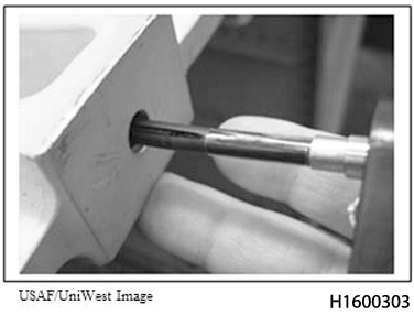
Figura 5.12. Alinhamento correto da sonda.
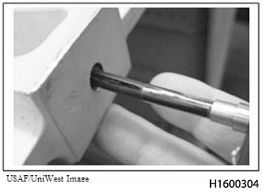
Figura 5.13. Alinhamento incorreto da sonda.
5.13
Espaçamento entre Sonda e Borda.
Ao inspecionar pequenas trincas
originadas nas bordas, o espaçamento entre sonda e borda pode se tornar
uma preocupação. Algumas abordagens para superar essas preocupações
são: aumentar a frequência da fonte geradora de correntes parasitas,
reduzir o tamanho físico da bobina e adicionar blindagem ao redor da
bobina da sonda. Blindagem adicional permitirá uma inspeção mais
próxima da borda devido ao menor volume de material detectado e
resultará em maior sensibilidade a falhas menores. O espaçamento entre
sonda e borda torna-se ainda mais preocupante quando a borda da peça
está em contato com uma peça ferromagnética, como um rolamento ou
bucha. Novamente, minimizar o volume de material detectado pela sonda
aliviará algumas dessas preocupações irrelevantes e otimizará a
resposta do sinal.
5.14
Interpretação do Sinal de Correntes Parasitas em Furos de Parafuso.
Um
dos requisitos mais importantes para detectar uma pequena trinca é que
a bobina passe sobre a trinca. Indiscutivelmente, a capacidade do
técnico de interpretar as respostas do sinal de correntes parasitas é
igualmente crucial para uma inspeção bem-sucedida. Para avaliar
completamente qualquer indicação, os técnicos devem utilizar as telas
de plano de impedância e de varredura (registro gráfico, Figura 5.14).
O plano
de impedância fornece as informações de fase, permitindo que o técnico
avalie se uma indicação é decorrente de ruído ou de uma trinca. A
Figura 5.15 ilustra por que a passagem de uma sonda de reflexão
diferencial sobre uma trinca resulta em uma indicação em forma de oito
("Lissajous") ou de circuito duplo na tela do instrumento. O registro
gráfico da varredura
mostra quantas indicações de falha estão presentes e, se configurado
corretamente, em qual posição circunferencial, a partir de um ponto de
referência, cada falha está localizada no furo. Usados em conjunto,
as telas de plano de impedância e de varredura permitem que o
técnico determine a orientação do sinal presente, quantas falhas estão
presentes e sua posição circular dentro do furo do fixador.
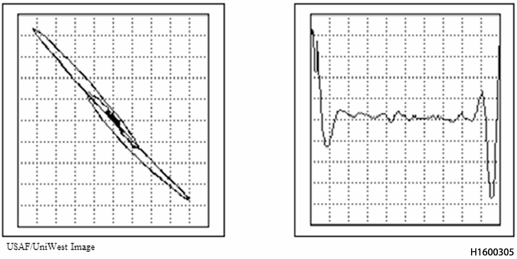
Figura 5.14. Mostrador do Plano de Impedância (Esquerda) e Registro Gráfico da Varredura (Direita).
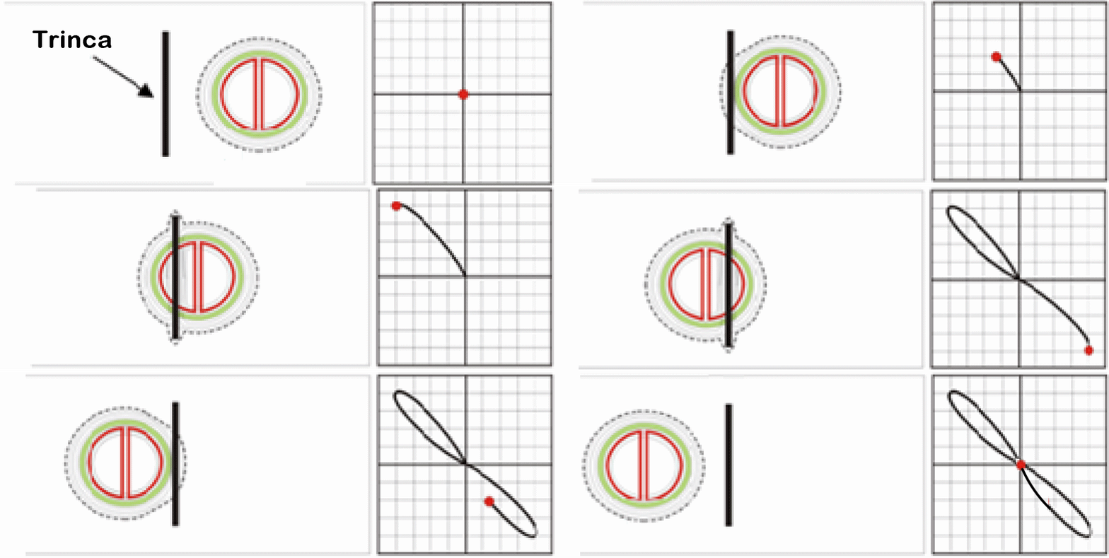
Figura 5.15. Respostas do Sinal de Correntes Parasitas em Furos de Parafusos a Partir de uma Trinca
- A medida que a sonda se move através da trinca o
trajeto das correntes parasitas vai se modificando com a circulação ao
redor e abaixo da trinca;
- Essa mudança é detectada pela bobina receptora 1 e como resultado, o ponto no plano de impedância move-se para cima;
- Com a continução de movimentação da sonda, a
distorção da corrente causa uma resposta máxima na bobina receptora 1 e
a resposta no plano de impedância alcança o máximo;
- Quando a trinca se localiza no centro das bobinas, o
fluxo de corrente se modifica ao redor da trinca e a distorção atinge
seu máximo;
- Entretanto, nessa posição ambas as bobinas sensoras
estão "sentindo" o mesmo campo e porque estão enroladas em
sentido contrário , o sinal resultante é zero (resposta nula);
- A medida que a sonda se move mais ainda, a bobina
receptora 2 agora "sente" a distorção da corrente e
como resultado o sinal no plano de impedâncias se move para baixo;
5.14.1
Furos Excêntricos.
Os efeitos de furos fora de circularidade ocorrem
frequentemente, dificultando muito a interpretação do
sinal e podendo levar a falsas indicações ou à perda de trincas. É
muito importante medir os furos dos fixadores antes da inspeção, caso
suspeite de uma condição fora de circularidade. Estudos demonstraram
que a detecção de trincas ainda é possível em diâmetros nominais abaixo
de 0,006 a 0,008 polegadas fora de circularidade; no entanto, a
resposta do sinal de trinca é ligeiramente distorcida. Acima desses
valores, os sinais de trinca são geralmente distorcidos, não são
distinguíveis do ruído e os níveis de ruído excedem os limites de
rejeição. Em aplicações em campo, furos fora de circularidade
normalmente apresentam níveis inaceitáveis de ruído de sinal. Os
parágrafos a seguir descrevem alguns dos efeitos observados nas
respostas de sinal de furos fora de circularidade.
5.14.1.1
Resposta "Tipo Poço" ["GOAL POST"} (sem trinca). À medida que a sonda gira no furo do
fixador, ela se comprime ao entrar na seção estreita (3-9 horas). Ao
entrar na seção mais larga (6-12 horas), ela se expande, mas a bobina
pode não tocar mais a superfície e, portanto, sofre lift-off O
resultado é um padrão semelhante a um poço no visor registro gráfico de varredura e
uma indicação no visor de impedância semelhante a uma indicação de
trinca, mas em um ângulo de fase diferente (Figura 5.16). Esse ruído
excessivo de lift-off é rejeitável .
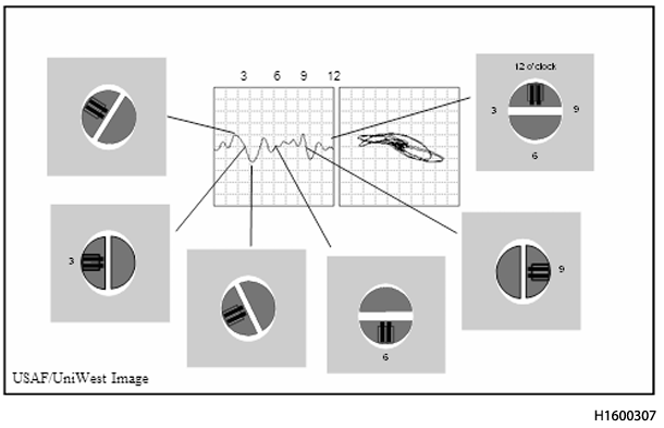
Figura 5.16. Resposta tipo poço em alumínio.
5.14.1.2
Resposta de ruído excessivo. Se houver uma trinca na seção estreita de
um furo fora do círculo, o efeito de lift-off pode mascarar ou
distorcer a resposta do sinal da trinca, dificultando a interpretação
da resposta da trinca (Figura 5.17). Mesmo que uma indicação semelhante
a uma trinca não estivesse presente, o furo na Figura 5.17 ainda seria
rejeitável, com base no ruído de elevação excessivo
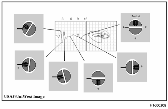
Figura 5.17. Resposta de Ruído Excessiva em Alumínio
5.14.1.3
Ruído Excessivo e Resposta a Trincas. Se houver uma trinca na seção
mais larga de um furo fora de circularidade, o efeito de lift-off tem
dois efeitos: pode mascarar ou distorcer a resposta do sinal da trinca
e reduz a amplitude do sinal (Figura 5.18). O furo na Figura 5.18 seria
rejeitável com base no ruído e devido a uma indicação semelhante a uma
trinca. Se o furo estiver severamente fora de circularidade, o efeito
de lift-off pode ser tão grande que não há resposta perceptível da
trinca.
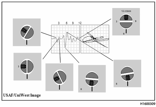
Figura 5.18. Ruído Excessivo e Resposta a Trincas em Alumínio
5.15 Furos de Fixadores Não Removíveis.
5.15.1
Inspeção Aplicação de Furos de Fixadores.
Se um fixador não puder ser
removido de um furo devido ao seu tipo ou localização, a inspeção ao
redor do fixador pode ser realizada para detectar trincas que se
desenvolvem sob a cabeça ou porca do fixador. O tamanho das trincas
detectáveis depende da distância que deve ser mantida entre a sonda e
a borda do fixador. Em muitos aspectos, essa aplicação é semelhante à
inspeção de trincas na borda de aberturas e recortes. Sondas grandes de
baixa frequência e sondas reflexivas deslizantes também podem ser
escaneadas sobre fixadores escareados e identificar trincas na 1ª, 2ª e
3ª camadas.
5.15.2
Espaçamento entre Sonda e Fixador.
Se necessário apenas para detectar
trincas relativamente grandes, como aquelas que se estendem entre dois
fixadores, a inspeção por correntes parasitas geralmente pode ser
realizada a uma distância suficiente das cabeças dos fixadores para
eliminar seu efeito na resposta das correntes parasitas. Quando
pequenas trincas precisam ser detectadas, a sonda deve ser posicionada
mais próxima da borda do fixador, e a distância entre a sonda e o
fixador deve ser mantida constante durante a varredura. Quando
fixadores fabricados com materiais magnéticos, como aço, são usados
em peças não magnéticas, um espaçamento relativamente grande deve ser
usado. Além disso, sondas blindadas podem ser usadas para minimizar a
distância entre a sonda e o fixador, permitindo a inspeção próxima ao
fixador.
5.15.3
Guias de Varredura ao Redor de Fixadores Não Removíveis.
Para fixadores
não ferrosos (não magnéticos), a cabeça do fixador pode ser usada como
guia da sonda. Somente os fixadores que se projetam da superfície da
peça e são concêntricos com o furo podem ser usados como guias. Para
fixadores com cabeças não concêntricas com os furos, como cabeças
hexagonais e serrilhadas, um colar acoplado à cabeça do fixador pode
ser usado como guia de varredura. A maioria das sondas blindadas pode
ser varrida ao redor de fixadores de aço sem a necessidade de um colar.
Os gabaritos devem ser posicionados concêntricos à cabeça do fixador
para garantir uma resposta relativamente consistente de um material sem
defeitos à medida que a sonda é guiada ao redor do fixador.
5.15.4
Seleção da Sonda.
Assim como em muitas outras aplicações de detecção de
falhas, recomenda-se o uso de sondas de raio de pequeno diâmetro. Essas
sondas permitem melhor visibilidade da localização da bobina da sonda e
maior flexibilidade no estabelecimento do espaçamento entre a sonda e o
fixador. Sondas de raio também são menos suscetíveis do que sondas de
superfície plana a variações de elevação com mudanças no ângulo entre a
sonda e a superfície.
5.15.5
Normas para Furos de Fixadores Não Removíveis.
Sempre que possível, as
normas para inspeção ao redor das cabeças de fixadores não removíveis
devem reproduzir o mais fielmente possível as condições da área de
inspeção. Caso não estejam disponíveis amostras trincadas que
representem o tamanho mínimo de trinca a ser detectado, podem ser
utilizadas ranhuras de eletroerosão cortadas nas bordas dos furos na
norma de referência. O material, a geometria, o tamanho do furo, o tipo
de fixador e a instalação devem ser os mesmos para a peça de referência
e para a área de inspeção, a menos que tenha sido estabelecida
correlação prévia com outras referências disponíveis. A duplicação da
geometria da peça na referência minimiza as diferenças de resposta
entre as referências e as trincas na peça.
5.16 Filetes e Cantos Arredondados.
5.16.1
Bordas (Incluindo Cantos e Raios).
Para a maioria das técnicas de
correntes parasitas, o fluxo é circular e paralelo à superfície da
peça. Se o fluxo de correntes parasitas interceptar uma borda, canto ou
raio da peça, o padrão circular é interrompido e as correntes parasitas
ficam confinadas a um volume menor. Essa ação altera a magnitude e a
distribuição das correntes parasitas e é conhecida como efeito de borda
(Figura 5.19). Conforme ilustrado, a densidade de corrente será
ligeiramente maior na borda da peça do que no interior. Isso resultará
em um ligeiro aumento na sensibilidade a descontinuidades localizadas
na borda.
5.16.2
Ocorrência de Trincas.
Cargas de flexão repetidas aplicadas a filetes e
raios (cantos arredondados) de uma peça podem levar a trincas por
fadiga. Trincas por fadiga geralmente ocorrem paralelas ao raio. Em
raios moldados, a trinca geralmente ocorre perto do centro do raio,
onde há afinamento máximo. Em filetes usinados ou raios de perfis
extrudados onde a espessura da peça é maior no centro do raio, é mais
provável que ocorram trincas de fadiga no ponto tangente ao raio. Às
vezes, podem ocorrer trincas por corrosão sob tensão nos raios e
filetes de peças usinadas onde são aplicadas tensões de tração ou áreas
com tensões de tração residuais são expostas. A trinca por corrosão sob
tensão é frequentemente promovida pelo acúmulo de umidade nesses
filetes e raios.
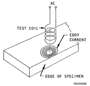
Figura 5.19. Distorção do Fluxo de Correntes parasitas na Borda de uma Peça
5.16.3
Requisitos de Equipamento para Filetes e Raios.
Em geral, nenhum
equipamento especial é necessário para a inspeção de filetes e raios.
Uma inspeção adequada pode ser realizada usando instrumentos de
correntes parasitas com uma sonda de ponta de raio ou um sistema de
ensaio equivalente. O raio da ponta da sonda deve ser menor que o raio
do filete a ser inspecionado para garantir um contato relativamente
constante entre a sonda e a peça e, assim, evitar variações excessivas
no levantamento. Para a inspeção das bordas de raios ou filetes, é
recomendável usar uma régua plástica fina para manter o espaçamento
entre a sonda e a borda no filete. Ocasionalmente, um dispositivo de
fixação semelhante ao usado para os raios de assento do talão em rodas
pode ser usado para filetes e raios. Dispositivos de fixação reduzem o
tempo de inspeção, melhoram a detectabilidade da inspeção e garantem
uma cobertura completa.
5.16.4
Padrões de Referência para Filetes.
O melhor padrão de referência é uma
peça real com uma falha real. Se isso não puder ser obtido, um corpo de
prova que represente a configuração da peça a ser testada deve ser
usado para a configuração. Portanto, é preferível ter um padrão do
mesmo material, acabamento e raio do filete a ser ensaiado. Uma ou
várias falhas podem ser colocadas na área de inspeção do padrão de
referência. O padrão deve conter pelo menos uma falha igual ou menor
que o tamanho de falha exigido pela inspeção. Padrões planos podem ser
usados se um padrão com a configuração necessária não estiver
disponível. A resposta de padrões planos difere muito pouco da resposta
de trincas ou ranhuras em filetes ou superfícies curvas se uma sonda de
raio com diâmetro substancialmente menor que o raio do filete for
usada. Ranhuras nas bordas não são intercambiáveis com ranhuras
localizadas longe da borda.
5.17 Corrosão.
5.17.1
Requisitos do Sistema de Ensaio para Detecção de Corrosão.
Os requisitos
do sistema de ensaio para detecção de corrosão dependem do tipo e da
profundidade da corrosão para a qual a inspeção é realizada. Para
corrosão por corrosão uniforme e para grandes pites, os sistemas de
medição de espessura fornecem ótima detectabilidade. Para pequenos
pites e pequenas áreas de esfoliação ou ataque intergranular, os
requisitos de inspeção tornam-se semelhantes aos para falhas
subsuperficiais. Instrumentação e sondas com uma ampla seleção de
frequências de operação podem ser necessárias para cobrir a ampla gama
de tipos de materiais e espessuras. Equipamentos de análise de plano de
impedância operados por bateria podem ser usados para detecção de
corrosão e têm muitas vantagens para essas aplicações na maioria das
situações de campo.
5.17.2
Tipos de Corrosão.
Corrosão é uma deterioração de metais por ação
química. A corrosão ocorre quando um líquido condutor, como água com
íons, permite que os elétrons se movam de uma peça de metal para outra,
ou de um ponto para outro na mesma peça de metal. Se sal, ou outra
fonte de íons, for adicionado à água, a condutividade é aumentada e a
taxa de corrosão aumenta. Até mesmo a condensação do ar úmido pode
fornecer água suficiente para que a corrosão ocorra. As principais
defesas contra a corrosão em aeronaves são o isolamento de metais
diferentes uns dos outros e a proteção das superfícies metálicas contra
a umidade. Embora a corrosão possa ser classificada de várias maneiras,
para fins de detecção, cinco formas principais são consideradas: (1)
corrosão uniforme, (2) corrosão por pites, (3) ataque intergranular,
(4) esfoliação e (5) corrosão sob tensão.
NOTA:
Mais
explicações sobre a teoria da corrosão podem ser encontradas no
Capítulo 3 do NAVAIR 01-1A-509-1/TO 1-1-689-1/TM 1-1500-344-23-1.
5.17.2.1
Ataque Uniforme.
A corrosão por ataque uniforme é caracterizada por uma
redução geral na espessura do metal, na qual algumas áreas podem ser
corroídas mais rapidamente do que outras. Essa forma de corrosão é
facilmente detectável visualmente em superfícies expostas. A corrosão
de superfícies inacessíveis de estruturas metálicas finas é detectável
por correntes parasitas, se houver acesso ao lado não corroído. A
detecção desse tipo de corrosão torna-se então uma questão de medição
da espessura, com algumas variações esperadas devido a pequenas áreas
com aumento da corrosão ou à presença de materiais metálicos na
superfície mais distante.
5.17.2.2
Pontas.
Pequenas áreas localizadas de corrosão são denominadas pites.
As pites podem variar de tamanho pontual a áreas relativamente grandes.
A detecção e a medição de pites de corrosão devem levar em consideração
essas possíveis variações.
5.17.2.3
Ataque Intergranular.
Em alguns materiais, incluindo muitas ligas
estruturais de alumínio, a corrosão ocorre preferencialmente ao longo
dos contornos de grão. Embora pequenas quantidades de corrosão por
pites possam ser observadas na superfície, a extensão do dano não é
facilmente observável visualmente devido às pequenas penetrações
semelhantes a trincas. Este tipo de ataque é particularmente aplicável
a ligas de alumínio.
5.17.2.4
Esfoliação.
A corrosão por esfoliação inicia-se ao longo dos contornos
de grãos paralelos à superfície e propaga-se a partir desses locais de
iniciação. Os produtos da corrosão forçam o metal para cima, resultando
em bolhas e descamação do metal. Esta forma de corrosão é mais
prevalente em ligas de alumínio estruturais, como 7075-T6.
5.17.2.5
Trincas de Corrosão sob Tensão.
A combinação de uma tensão residual ou
de serviço aplicada constantemente e um ambiente corrosivo pode levar à
trinca por corrosão sob tensão em muitos metais de alta resistência. A
tensão residual pode resultar de tratamento térmico, usinagem,
conformação, ajustes por contração, soldagem e desengate de montagem.
Dependendo do tipo de metal e do ambiente corrosivo, a trinca por
corrosão sob tensão pode ou não estar associada a outras formas de
corrosão. Esta forma de corrosão é principalmente uma trinca e sua
detecção foi abordada em aplicações relacionadas à detecção de trincas
5.17.3
Seleção de Frequência.
A escolha da frequência depende do tipo de
corrosão a ser detectada e da espessura do material através do qual a
inspeção está sendo realizada. Frequências mais altas favorecem a
resolução de pequenas cavidades ou pequenas áreas de corrosão
intergranular ou esfoliação. Frequências mais baixas aumentam a
profundidade de penetração.
5.17.4
Seleção da Sonda.
A sonda deve corresponder à frequência com que a
inspeção de corrosão é realizada. Quando mais de um modelo de sonda é
operável na frequência de inspeção, a geometria da peça e da sonda são
os fatores determinantes na seleção da sonda. Para áreas de contato
estreitas, uma sonda de menor diâmetro pode ser vantajosa. Sondas de
maior diâmetro proporcionam uma média maior da espessura e proporcionam
uma sensibilidade um pouco melhor em áreas mais espessas.
5.17.5
Padrões de Referência para Corrosão.
Devido à ação única de cada tipo
de corrosão e seu efeito sobre a condutividade, os padrões de
referência devem ser fabricados com a mesma liga, têmpera e espessura
do material a ser inspecionado. Quando superfícies de contato estão
envolvidas na detecção de corrosão, o padrão deve ser construído para
simular a junta, incluindo calços não condutores para espessura de
folga, tinta e primer. Padrões para corrosão por pites também podem ser
usados para esfoliação e ataque intragranular. Os padrões também
devem ter aproximadamente a mesma geometria da peça.
5.17.6
Procedimento de Inspeção - Detecção de Corrosão.
A detecção de corrosão
com técnicas de correntes parasitas é aplicada a revestimentos de
aeronaves quando a corrosão pode ocorrer em superfícies internas
inacessíveis. A corrosão geralmente ocorre em áreas onde a umidade está
retida. Se for esperado um afinamento relativamente uniforme, a
detecção da corrosão pode ser simplesmente uma questão de medição da
espessura. Na maioria dos casos, a corrosão está confinada a áreas
menores e localizadas, de diâmetro relativamente pequeno. À medida que
a espessura do revestimento aumenta, a sensibilidade a pequenas áreas e
profundidades rasas de corrosão é reduzida.
5.17.7 Part Preparation. Prior to inspection, all foreign material
should be removed from the area to be inspected. Any roughness, sharp
edges, or protrusions that could damage the probe or cause errors in
readings should be removed by light sanding within the limits of the
applicable TO. The locations of all fasteners, edges, and changes in
structure on the far side of the inspection surface should be
established and marked with an approved removable marker to aid in the
interpretation of inspection results. Paint removal is not required if
it is relatively uniform and not loose or flaking. Because of the wide
variety of corrosion attack, inspection SHALL be performed in
accordance with the applicable TO
5.17.7
Preparação da Peça.
Antes da inspeção, todo material estranho deve ser
removido da área a ser inspecionada. Quaisquer rugosidades, arestas
vivas ou saliências que possam danificar a sonda ou causar erros nas
leituras devem ser removidas por lixamento leve, dentro dos limites da
TO aplicável. As localizações de todos os fixadores, arestas e
alterações na estrutura no lado mais distante da superfície de inspeção
devem ser estabelecidas e marcadas com um marcador removível aprovado
para auxiliar na interpretação dos resultados da inspeção. A remoção da
tinta não é necessária se ela estiver relativamente uniforme e não
estiver solta ou descascando. Devido à ampla variedade de ataques por
corrosão, a inspeção DEVE ser realizada de acordo com a Norma.
5.18 Medição de Condutividade em Campo.
Instrumentação de
correntes parasitas é utilizada para determinar a condutividade
elétrica em condições de produção e de campo. Os instrumentos de
correntes parasitas são calibrados de acordo com padrões de
condutividade conhecidos. Quando disponíveis, são utilizados
instrumentos projetados especificamente para medição de condutividade.
Esses instrumentos medem a condutividade diretamente em % IACS.
5.18.1
Condutividade de Ligas de Alumínio.
A medição da condutividade é
aplicada com mais frequência a ligas de alumínio. Essa aplicação
resulta do amplo uso de ligas de alumínio na indústria aeroespacial e
da ampla variação na condutividade elétrica e nas propriedades
mecânicas entre diferentes ligas e tratamentos térmicos. Para a maioria
das ligas de alumínio de uso comum, faixas de condutividade específicas
foram estabelecidas para cada liga e têmpera. As faixas de
condutividade para a maioria das ligas de alumínio comumente usadas em
aplicações estruturais de aeronaves estão listadas na Tabela 8-4, na
Seção 8. Esses valores representam um conjunto de valores obtidos
de vários fabricantes de fuselagens e agências governamentais. As
faixas incluem todos os valores obtidos para tratamentos térmicos
padrão, exceto os valores extremos obtidos de uma ou duas fontes que
estavam claramente fora das faixas de todas as outras listas. Se um
valor de condutividade medido para uma liga de alumínio e têmpera
estiver fora da faixa aplicável, suas propriedades mecânicas DEVEM ser
consideradas suspeitas. A medição dos valores de condutividade DEVE
estar de acordo com SAE-AMS-H-6088, ASTM E1004 ou outra norma adequada.
5.18.2
Efeitos do Tratamento Térmico na Condutividade do Alumínio.
Uma liga de
alumínio apresenta a maior condutividade e a menor resistência quando
está totalmente recozida. Após a têmpera a partir da temperatura de
tratamento térmico em solução, a resistência aumenta e a condutividade
diminui. Muitas ligas de alumínio permanecem instáveis por um período
considerável após o tratamento térmico em solução, mesmo quando
mantidas à temperatura ambiente durante esse período. Uma certa
migração de átomos ocorre para iniciar a formação de partículas
submicroscópicas. Esse processo, às vezes chamado de envelhecimento
natural, aumenta a resistência da liga, mas não tem efeito sobre a
condutividade ou apenas reduz ligeiramente seu valor. Algumas ligas de
alumínio permanecem instáveis por períodos tão longos após a têmpera
que nunca são utilizadas na condição de tratamento térmico em solução
(por exemplo, 7075). Se uma liga tratada termicamente em solução for
endurecida por precipitação por aquecimento a uma temperatura
relativamente baixa (geralmente 93-233 °C), os átomos de liga formam
pequenas partículas. Em um tamanho e distribuição de partículas
críticos, a resistência da liga de alumínio atinge o máximo. A
condutividade aumenta durante o endurecimento por precipitação ou o
processo de envelhecimento artificial. Se o envelhecimento for
prolongado além do ponto em que a resistência ideal é obtida, a
resistência diminuirá, mas a condutividade continuará a aumentar.
5.18.3
Discrepâncias no Tratamento Térmico de Ligas de Alumínio.
Variações em
relação às práticas de tratamento térmico especificadas podem resultar
em ligas de alumínio com resistências abaixo dos níveis exigidos. As
discrepâncias no tratamento térmico incluem alterações ou aplicação
incorreta dos seguintes processos:
- Temperatura do tratamento térmico da solução
- Tempo de tratamento térmico da solução
- Prática de têmpera Temperatura de envelhecimento
- Tempo de envelhecimento Temperatura e tempo de recozimento
- Aplicação de temperatura descontrolada
5.18.4 Aplicações da Medição de Condutividade.
NOTA:
As
Tabelas do Capítulo 4, Seção 8, fornecem valores e faixas de
condutividade para referência. No entanto, ao determinar a
operacionalidade de um componente ou estrutura de aeronave com base na
condutividade, a faixa de condutividade apropriada deve ser
identificada ou confirmada por engenharia especializada.
5.18.5
Separação de Ligas e Têmperas.
A medição de condutividade pode ser
usada para separar misturas de duas ou mais ligas e/ou têmperas. A
separação é possível quando a condutividade elétrica de cada grupo é
claramente diferente. O processo de separação pode ser realizado com um
instrumento calibrado em % IACS
5.18.6 Medição de Condutividade e Materiais Magnéticos.
O
uso de instrumentos de uso geral pode ser estendido à separação de
materiais magnéticos onde o produto da permeabilidade e da
condutividade de cada uma das ligas é claramente diferente. Medidores
de condutividade não medem a condutividade de materiais magnéticos.
5.18.7
Aplicação Típica.
Técnicas de correntes parasitas são utilizadas para
separar peças metálicas ou matérias-primas de geometria semelhante que
perderam a identificação da liga e/ou têmpera e se misturaram durante a
fabricação ou armazenamento. Tais procedimentos podem ser aplicados em
qualquer etapa do processamento, armazenamento ou serviço do material.
5.18.8
Controle do Tratamento Térmico.
A relação entre a condutividade
elétrica e as condições do tratamento térmico permitiu o uso de
técnicas de correntes parasitas para verificar a adequação do
tratamento térmico em ligas de alumínio. Nesta aplicação, medições de
condutividade por técnicas de correntes parasitas são utilizadas para
complementar uma quantidade mínima de ensaios de tração e/ou dureza. As
medições de condutividade por correntes parasitas são particularmente
valiosas para determinar a uniformidade do tratamento térmico de
estruturas de ligas de alumínio grandes e complexas quando amostras de
tração não estão disponíveis e a geometria da peça limita o acesso para
ensaios de dureza. A adequação do tratamento térmico de ligas de
alumínio é determinada pela conformidade do material com as faixas de
condutividade preestabelecidas. Este método de controle do tratamento
térmico tem sido amplamente aplicado a ligas de alumínio. Técnicas de
correntes parasitas são utilizadas para avaliar o tratamento térmico de
aços. Geralmente, instrumentação mais sofisticada é utilizada para
aços, mas instrumentos de uso geral podem ser utilizados para muitas
aplicações. Padrões de aceitação são geralmente utilizados para
inspeção de aços por correntes parasitas. A medição da condutividade é
aplicada em menor grau para o controle do tratamento térmico de ligas
de cobre e magnésio. Técnicas de correntes parasitas podem ser
utilizadas para o controle do tratamento térmico em qualquer sistema de
ligas onde faixas de condutividade ou valores de permeabilidade
consistentes, porém diferentes, ocorrem com as diversas condições de
tratamento térmico. A medição da condutividade não foi estabelecida
como um método para determinar a resposta ao tratamento térmico em
ligas de titânio. As diferenças na condutividade entre as diversas
condições de tratamento térmico para a maioria das ligas de titânio são
insuficientes para permitir a determinação da têmpera.
5.18.9
Determinação de Danos por Calor e Fogo.
Uma aplicação comum da medição
de condutividade em aplicações de campo é a determinação de danos por
calor e/ou fogo em estruturas de aeronaves. Devido ao amplo uso de
ligas de alumínio em estruturas de aeronaves e sua sensibilidade a
perdas de propriedades mecânicas em temperaturas relativamente baixas,
a maior experiência e dados foram gerados para esses materiais. Danos
por calor e fogo em outros metais podem ser detectados se as
temperaturas se tornarem altas o suficiente para afetar a
condutividade, a permeabilidade e as propriedades mecânicas. Danos são
detectados em ligas de alumínio como mudanças na condutividade em
relação à faixa especificada para a liga e têmpera que estão sendo
inspecionadas. Danos por calor e fogo geralmente variam em uma peça
devido à aplicação não uniforme de calor. A aplicação não uniforme de
calor, por sua vez, resulta em variações na condutividade elétrica. A
menos que a temperatura e o tempo de aplicação de calor sejam
conhecidos, ou que o teste seja realizado em várias peças com o mesmo
histórico de aplicação de calor, valores quantitativos de propriedades
mecânicas não podem ser estabelecidos a partir dos valores de
condutividade elétrica. Os testes de dureza e a medição de
condutividade fornecem uma boa indicação de danos por calor e fogo.
Ambos os métodos de teste devem ser realizados para se ter uma ideia da
quantidade de dano.
5.18.10
Medição de Condutividade.
Para determinar a condutividade diretamente,
estão disponíveis instrumentos de correntes parasitas que fornecem um
valor de condutividade em % IACS. Instrumentos de medição de % IACS
geralmente requerem apenas dois padrões de condutividade conhecidos
para calibração. Se não houver equipamento de medição direta de
condutividade, equipamentos de correntes parasitas de uso geral podem
ser adaptados para medir a condutividade. O uso de equipamentos de uso
geral requer um número maior de padrões para estabelecer uma curva de
calibração. O número de padrões necessários para uma aplicação de
medição de condutividade é determinado pela faixa de condutividade a
ser coberta e pela precisão necessária. Equipamentos de uso geral
também podem ser usados em uma função passa-não-passa para separar
metais acima e abaixo de um valor de condutividade especificado. Um
padrão representando a condutividade mínima aceitável ou não permitida
deve estar disponível.
5.18.11 Equipment for Magnetic Materials. Impedance plane analysis instruments can be used to measure the conduc
tivity of ferromagnetic materials because the permeability and conductivity can be separated in phase. The combination of
conductivity and permeability, in many cases, can be related to variations in alloy, temper, and strength. General purpose me
ter type instruments can then be used to separate or grade various levels of properties. The number of standards required
depends on the number of categories of materials to be established.
5.18.11
Equipamentos para Materiais Magnéticos.
Instrumentos de análise de
plano de impedância podem ser usados para medir a condutividade de
materiais ferromagnéticos porque a permeabilidade e a condutividade
podem ser separadas em fase. A combinação de condutividade e
permeabilidade, em muitos casos, pode estar relacionada a variações na
liga, têmpera e resistência. Instrumentos de medição de uso geral podem
ser usados para separar ou classificar vários níveis de propriedades.
O número de padrões necessários depende do número de categorias de
materiais a serem estabelecidas.
5.19 Efeitos das Variações nas Propriedades dos Materiais.
5.19.1
Condutividade.
Variações na condutividade podem ocorrer em metais como
resultado de tratamento térmico inadequado ou como resultado da
exposição a temperaturas excessivas durante o serviço e o trabalho a
frio. Essas são as condições para as quais a inspeção por correntes
parasitas geralmente é realizada. Variações na condutividade podem
advir de outras fontes. A separação de elementos durante a
solidificação de metais pode levar a diferenças localizadas ou
uniformes na condutividade. Por exemplo, pode haver uma variação na
condutividade com o aumento da profundidade abaixo da superfície da
peça, particularmente em seções mais pesadas que não foram trabalhadas
extensivamente. Pequenas diferenças no tempo de tratamento térmico,
temperatura ou taxas de têmpera impostas por limitações nas instalações
de tratamento térmico ou mudanças na configuração da peça também levam
a variações na condutividade de uma peça. O trabalho a frio localizado
de metais, quando não seguido por tratamento térmico para aliviar a
tensão residual, pode reduzir a condutividade elétrica. Muitas das
variações são consideradas normais ao processamento das peças e a
condutividade está dentro da faixa aceitável para a especificação e
têmpera da liga. Condutividade fora da faixa especificada para uma dada
liga e têmpera deve ser considerada inaceitável e investigações
adicionais devem ser realizadas usando técnicas de teste de dureza.
5.19.2
Efeitos de Borda.
Se o campo eletromagnético da sonda for afetado pela
geometria da borda da peça, ocorrerá um erro na medição da
condutividade. A sonda deve ser localizada a vários diâmetros de sonda
de distância da borda ou limite de transição mais próximo.
5.19.3
Curvatura. Efeitos de lift-off causados pelo encaixe da sonda na
superfície curva causarão um erro na medição da condutividade. Em
superfícies curvas, a menor sonda prática deve ser usada para minimizar
os efeitos de elevação.
5.19.4
Materiais Revestidos.
O revestimento afetará a condutividade medida do
metal base. O grau em que o revestimento afetará o valor obtido depende
da condutividade do revestimento, da espessura do revestimento e da
frequência de operação. As aplicações atuais geralmente se limitam a
ligas de alumínio "Alclad" na faixa de 0,050 a 0,080 polegadas de
espessura, utilizando medidores de condutividade com frequências de
operação de 60 kHz. Faixas especiais de condutividade são necessárias
para ligas de alumínio revestidas. As espessuras do revestimento, que
geralmente são baseadas em uma porcentagem da espessura total, podem
variar ligeiramente devido às tolerâncias normais. A 60 kHz, as
leituras de condutividade de ligas de alumínio com espessura inferior a
0,050 polegadas são afetadas tanto pela espessura do revestimento
quanto pela espessura da peça. Os testes de correntes parasitas de
sistemas complexos de revestimento ainda estão, em sua maior parte, em
fase experimental.
5.19.5
Permeabilidade Magnética.
A medição direta da condutividade elétrica
por medidor é aplicável a materiais não magnéticos com permeabilidade
magnética relativa de um ou quase um. Se a permeabilidade magnética
exceder um, ocorrerá um desequilíbrio de ponte no sistema do medidor,
que não pode ser separado da medição de condutividade, e leituras
errôneas serão obtidas. Por esse motivo, a condutividade de aços,
níquel e outros materiais magnéticos não pode ser determinada com
medidores convencionais de condutividade por correntes parasitas.
Alguns aços inoxidáveis (por exemplo, série 300) são essencialmente
não magnéticos na condição recozida, mas pequenas quantidades de
trabalho a frio ou exposição a temperaturas extremamente baixas podem
causar a transformação em uma estrutura magnética. Equipamentos de
análise de plano de impedância podem separar facilmente a
permeabilidade magnética da condutividade, permitindo uma medição
precisa da condutividade de materiais ferromagnéticos.
5.19.6
Geometria.
Qualquer alteração na configuração da peça que afete a
distribuição ou penetração de correntes parasitas resultará em leituras
errôneas de condutividade elétrica. As seguintes fontes de erro estão
incluídas nessas categorias:
- Proximidade de bordas parciais ou estrutura adjacente
- Espessura do metal menor que a profundidade efetiva de penetração no metal
- Curvatura excessiva da superfície da peça
5.19.7
Espessura do Metal.
Se a espessura do metal for menor que a penetração
efetiva das correntes parasitas, a condutividade medida será diferente
do valor real. Observe que a profundidade de penetração efetiva é
aproximadamente três vezes a profundidade padrão de penetração. Com
equipamentos de medição, é importante determinar a frequência de
operação do instrumento. A frequência de operação não deve exceder a
profundidade de penetração efetiva do material a ser testado.
Equipamentos de análise de plano de impedância possuem uma ampla faixa
de frequências de operação, e a frequência pode ser ajustada para
limitar a penetração a menos que a profundidade efetiva. A profundidade
padrão pode ser determinada usando a equação do Seção 8, Parágrafo 8.7. Réguas
de cálculo especiais estão disponíveis para calcular a profundidade de
penetração. A profundidade efetiva é aproximadamente três vezes maior
que a profundidade padrão calculada por esta equação. A espessura do
material deve ser maior que a profundidade efetiva, caso contrário,
ocorrerão erros na medição da condutividade.
5.20 Efeitos das Variações nas Condições de Ensaio.
5.20.1
Frequência.
Como a frequência afeta a distribuição das correntes
parasitas dentro da peça de teste, ela afeta a espessura mínima que
pode ser medida sem ajustes especiais. Frequências mais altas permitem
a medição de metais mais finos sem compensação de espessura. Selecione
uma frequência tal que a profundidade efetiva de penetração (2,6 )
esteja contida no metal sendo testado para uma medição de condutividade
razoavelmente precisa. No entanto, as frequências mais altas são mais
fortemente afetadas por variações localizadas na condutividade ou por
revestimentos e revestimentos condutores em metais. Frequências
excessivamente altas NÃO DEVEM ser usadas para medições de
condutividade.
5.20.2
Sondas para Medições de Condutividade.
Com instrumentos projetados para
medição de condutividade, as sondas são cuidadosamente combinadas com
os instrumentos e geralmente são obtidas do fabricante do instrumento.
As sondas para instrumentos de medição de condutividade são maiores do
que aquelas normalmente usadas para detecção de defeitos. Este projeto
permite o cálculo da média da condutividade em uma área relativamente
grande. As sondas são projetadas com sapatas de plástico ou cerâmica
para evitar danos à bobina. Com o uso contínuo, o desgaste na face da
sonda reduz a distância da bobina à superfície e a calibração não pode
ser obtida. Conforme ocorre o desgaste, a sapata da sonda deve ser
trocada e o instrumento recalibrado.
5.20.3
Efeitos do Lift-Off na Condutividade.
Instrumentos de medição de
condutividade do tipo medidor por correntes parasitas frequentemente
possuem um ajuste de lift-off predefinido. O ajuste de lift-off
geralmente é definido durante a calibração dos instrumentos. Os manuais
de manutenção aplicáveis descrevem os procedimentos que podem ser
realizados por pessoal de END treinado. Com o desgaste da sonda e
alterações nos componentes elétricos do instrumento ao longo do tempo,
o ajuste de lift-off pode mudar. Portanto, quando as medições de
condutividade devem ser realizadas em superfícies ásperas ou através de
revestimentos finos não condutores, o ajuste de lift-off DEVE ser
verificado antes da realização das medições. Após a calibração de um
instrumento em relação aos padrões de condutividade, o ajuste de
lift-off DEVE ser verificado em relação a uma amostra com condutividade
representativa da peça de teste. Lift-off, maior que o valor do ajuste
de lift-off predefinido (se houver), resulta em erros nas leituras de
condutividade.
5.20.4
Efeitos da Temperatura nas Medições de Condutividade.
Temperaturas mais
altas aumentam a atividade térmica dos átomos em uma rede metálica. A
atividade térmica faz com que os átomos vibrem em alta amplitude em
torno de sua posição na rede. Essa vibração térmica dos átomos aumenta
as chances de colisão com elétrons no material. Isso aumenta a
resistência ao fluxo de elétrons, diminuindo assim a condutividade do
metal. Temperaturas mais baixas reduzem a oscilação térmica dos átomos,
resultando em um aumento da condutividade elétrica. A condutividade dos
padrões é geralmente determinada a uma temperatura específica; 20 °C
(68 °F) é a mais comumente usada. Valores típicos de condutividade e
faixas de condutividade permitidas também são estabelecidos
aproximadamente a essa temperatura. Se todas as medições de calibração
e condutividade do instrumento pudessem ser realizadas a essa
temperatura, erros na medição de condutividade relacionados à variação
de temperatura não ocorreriam e/ou a compensação de temperatura não
seria necessária. Em aplicações de campo, as temperaturas de teste
podem estar em qualquer lugar na faixa de 0 °F a 120 °F. A menos que
precauções sejam tomadas na seleção dos padrões, calibração do
instrumento e testes, erros ocorrerão nos valores de condutividade
medidos. Duas maneiras pelas quais leituras errôneas podem ser obtidas
são:
- Diferença de temperatura entre os padrões e a parte de teste
- Diferença
na temperatura na qual a condutividade do padrão foi originalmente
estabelecida e a temperatura na qual a calibração do instrumento e as
medições de condutividade são realizadas
5.20.5
Para evitar erros devido a diferenças de temperatura entre o padrão e a
peça de teste, o instrumento e os padrões DEVEM se estabilizar na
temperatura da peça de teste antes da calibração e das medições de
condutividade serem realizadas. As medições NÃO DEVEM ser realizadas se
a temperatura da peça e dos padrões diferir em mais de 10°F. Mesmo que
o padrão e a peça de teste estejam à mesma temperatura, erros na
determinação dos valores de condutividade ocorrem quando a temperatura
de medição difere da temperatura na qual a condutividade dos padrões
foi originalmente estabelecida. A magnitude do erro aumenta à medida
que essa diferença de temperatura aumenta.
5.21
Detecção de Falhas.
Trincas
induzidas por serviço em estruturas de
aeronaves são geralmente causadas por fadiga ou corrosão sob tensão.
Ambos os tipos de trincas se iniciam na superfície de uma peça. Se essa
superfície for acessível, seja por contato direto com a superfície ou
pela penetração do campo de correntes parasitas através do material, a
CP pode ser realizada com um mínimo de preparação da peça e um alto
grau de sensibilidade. Ao estabelecer uma técnica de correntes
parasitas para detecção de trincas, os seguintes fatores devem ser
considerados:
- Capacidades do sistema de teste
- Tipo de material a ser inspecionado
- Acessibilidade da área de inspeção
- Localização e tamanho das fissuras a serem detectadas
5.21.1
Capacidades do Sistema de Ensaio.
O sistema de teste para detecção de
trincas inclui a(s) sonda(s), o instrumento de correntes parasitas,
quaisquer instrumentos adicionais de registro ou medição e padrões de
referência. Uma grande variedade de unidades de correntes parasitas é
fabricada para CP de uso geral. Instrumentos de inspeção por correntes
parasitas de uso geral são utilizados para detecção de falhas. Na
indústria aeroespacial, poucos instrumentos de correntes parasitas de
uso geral utilizam displays de medidores. Na maioria dos casos, são
utilizados displays bidimensionais do plano de impedância que exibem a
análise detalhada de fase e amplitude.
5.21.1.1
Seleção da Sonda.
A principal consideração na seleção de uma sonda de
correntes parasitas é o tipo de inspeção que está sendo realizada. Para
detectar pequenas trincas, uma bobina de sonda blindada de pequeno
diâmetro com um núcleo de ferrite é desejável para concentrar o campo
induzido em um pequeno volume. Uma pequena trinca tem um efeito
proporcionalmente maior em um campo de sonda pequeno do que em um campo
de sonda grande. No caso de bobinas envolventes ou bobinas internas
serem usadas, bobinas curtas ou estreitas são preferidas para inspeção
de pequenas condições localizadas. O espaçamento das bobinas deve ser
considerado ao determinar a resolução necessária. A bobina ou sonda
deve corresponder à faixa de frequência e à impedância de saída do
instrumento que está sendo usado. Em geral, rachaduras cujos
comprimentos são menores que a metade do diâmetro da bobina são
difíceis de detectar.
5.21.1.1.1
Carcaças de Sonda.
A carcaça da maioria das sondas de superfície de uso
geral tem configuração cilíndrica e diâmetros de 1/8 a 3/8 de polegada.
As sondas podem ser blindadas com metal não permeável (mu) ou ferrite
para concentrar o campo. Quando for necessária a detecção de defeitos
ao redor de fixadores, em raios ou adjacentes a bordas, geralmente é
vantajoso ter uma ponta pontiaguda ou pequena e arredondada na
extremidade da sonda. A extremidade pontiaguda permite que a sonda seja
inserida mais próxima da superfície de inspeção, ou borda, e permite
melhor visibilidade da posição da bobina da sonda. As vantagens de uma
sonda pontiaguda para essas aplicações são ilustradas na Figura 5.20.
Para inspeção de furos de parafusos, são fabricadas sondas especiais
que permitem o contato com a lateral do furo em qualquer nível
desejado. Para áreas de inspeção onde a acessibilidade é um problema ou
onde o posicionamento da sonda é crítico, geralmente é desejável
fabricar carcaças de sonda especiais como um auxílio na realização da
inspeção. O uso de alojamentos especiais pode reduzir
significativamente a perda de sensibilidade associada à oscilação e à
decolagem da sonda durante a varredura. Quando grandes quantidades de
peças devem ser inspecionadas, sondas especiais apresentam uma vantagem
distinta, pois permitem a redução do tempo de inspeção por unidade.
Procedimentos de teste e ordens técnicas para a CP de componentes
específicos de aeronaves DEVEM especificar a sonda e os acessórios
especiais, podendo também especificar o projeto. Estudos de
probabilidade de detecção indicaram que guias de sonda e acessórios
especiais aumentam a confiabilidade da inspeção e DEVEM ser usados em
vez da varredura à mão livre.
5.21.1.1.2
Tipos de Sonda.
Os quatro tipos diferentes de sonda são sondas
absolutas, diferenciais, de refletância e de campo remoto. Cada tipo de
sonda é discutido na Seção 4, Parágrafo 4.2.1.
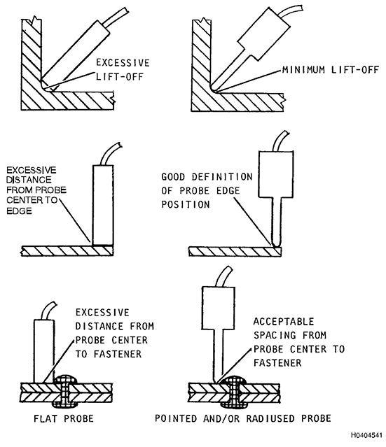
Figura 5.20. Vantagens das Sondas Pontiagudas e Arrendodadas para CP
5.21.2
Material de Inspeção.
O material com o qual a peça de inspeção é
fabricada é de fundamental importância ao determinar se a inspeção por
correntes parasitas deve ser usada e as limitações envolvidas com este
método. A condutividade e a permeabilidade magnética influenciam os
requisitos de frequência, a escolha do instrumento, a relação
sinal-ruído, as necessidades de filtragem, a sensibilidade resultante e
a confiabilidade da inspeção. Se for necessário detectar rachaduras
superficiais em material ferromagnético, pode-se usar uma alta
frequência para limitar a penetração ou um filtro passa-alta para
minimizar os problemas de permeabilidade.
5.21.3
Acessibilidade.
A maioria dos equipamentos de correntes parasitas
atualmente disponíveis para uso em campo é pequena, portátil e
alimentada por bateria. Isso permite sua operação em locais
relativamente apertados. No entanto, a inspeção por correntes parasitas
só é viável para condições superficiais ou próximas à superfície devido
à sua profundidade de penetração limitada. Por esse motivo, o acesso
direto à superfície a ser inspecionada é geralmente preferível. Deve
haver liberdade de movimento suficiente na área a ser inspecionada para
permitir o posicionamento e a movimentação da sonda para detectar ou
medir a variável especificada. A área de inspeção deve ser visível para
permitir que o inspetor determine a posição da sonda. Alternativamente,
uma sonda especial, um dispositivo de fixação ou uma guia podem ser
usados para posicionar e manter as sondas no local necessário. A
extensão da desmontagem necessária para a inspeção deve ser definida
nos procedimentos escritos aplicáveis.
5.21.4
Requisitos de Frequência.
À medida que a frequência do ensaio de
correntes parasitas é aumentada para uma aplicação específica de
correntes parasitas, as correntes parasitas são confinadas a um volume
menor adjacente à bobina da sonda de inspeção. Essa concentração
aumenta a proporção de correntes parasitas geradas interceptadas por
uma pequena trinca ou outro defeito. Frequências mais altas devem,
então, fornecer melhor resposta aos menores defeitos. Essa afirmação é
válida em geral, mas outras condições podem limitar a sensibilidade ao
usar frequências mais altas. Em alguns instrumentos, altas perdas por
indução limitam a saída do instrumento nessas frequências mais altas.
Frequências mais baixas podem ser necessárias para maior penetração na
detecção de falhas subterrâneas ou superficiais distantes. A
sensibilidade ideal a trincas ou outras falhas geralmente ocorre em
faixas de frequência específicas para cada combinação de metal, tamanho
da falha e profundidade da falha. As faixas de frequência de operação
podem ser estabelecidas para cada aplicação usando a profundidade de
penetração calculada usando a condutividade e a permeabilidade do
material. Esses cálculos DEVEM ser confirmados com o uso de padrões de
referência que simulem as falhas previstas a serem detectadas.
5.21.5
Relação Sinal-Ruído.
À medida que o ganho de um sistema de ensaio é
aumentado, um ruído elétrico de fundo será observado. Isso pode ser
representado por movimentos erráticos do medidor, sinais de fundo
excessivos em um display de forma de onda ou padrões aleatórios
excessivos em um registrador. Esse "ruído" pode ser o resultado de
variações aleatórias no sistema elétrico do instrumento de teste,
variações normais nas propriedades do material ou sinais elétricos
dispersos de outros dispositivos elétricos. A relação sinal-ruído não é
uma função apenas do instrumento, mas também depende das variações de
lift-off, acabamento superficial, condutividade e permeabilidade dentro
da parte de inspeção. Para que um instrumento de teste de correntes
parasitas ou qualquer outro instrumento de teste elétrico seja útil,
ele deve fornecer informações sobre o sinal de falha maiores do que o
ruído de fundo do sistema de teste. Caso contrário, o inspetor não
conseguiria ver a diferença entre o sinal de falha e o ruído de fundo.
Para máxima confiabilidade em CP, uma alta relação sinal-ruído é
desejável. Nenhuma relação sinal-ruído específica é obrigatória, mas um
mínimo de 3 para 1 é desejável para a detecção de falhas.
5.21.6
Relação sinal-ruído e sensibilidade.
À medida que o tamanho da trinca a
ser detectada diminui, o ganho ou a sensibilidade da instrumentação de
correntes parasitas deve ser aumentado para fornecer indicações
legíveis a partir de pequenas trincas. O ganho maior resulta em maiores
indicações a partir de pequenas trincas. O ganho maior também resulta
em maior resposta de variáveis diferentes de trincas e o nível de
ruído aumenta. Isso diminui a relação sinal-ruído, dificultando a
observação da indicação de uma descontinuidade pequena. A diminuição da relação
sinal-ruído diminui a confiabilidade da inspeção. Portanto, um aumento
no ganho aumentará a amplitude do sinal da falha, bem como o nível de
ruído. Portanto, a sensibilidade útil deve ser medida em relação ao
ruído do sistema de ensaio.
5.21.7
Influência da frequência no ruído.
Aumentar a frequência operacional do
CP melhora a sensibilidade a defeitos próximos à superfície, mas também
tende a aumentar o ruído de fatores relacionados à superfície, como
arranhões na decolagem, superfície áspera e oscilação da sonda.
5.21.8
Técnicas de Supressão.
Técnicas de supressão são utilizadas para
eliminar ou reduzir a resposta do instrumento a uma ou mais variáveis
de inspeção, permitindo uma melhor identificação de alterações nos
parâmetros de interesse durante a inspeção por correntes parasitas.
Quando o visor é girado conforme indicado anteriormente, as variações
de elevação produzem pouco ou nenhum sinal na direção vertical. Embora
o sinal de trinca seja predominantemente horizontal, ele possui um
componente vertical significativo. Este componente vertical pode ser
amplificado independentemente e monitorado visual ou eletronicamente.
Um alarme de caixa (gate) pode ser usado para monitorar eletronicamente
o componente vertical das indicações e disparar alarmes visíveis e
sonoros no equipamento para chamar a atenção do inspetor. O alarme de
caixa típico é um retângulo cuja posição, altura e largura podem ser
ajustadas para monitorar seletivamente uma parte do plano de
impedância. Os alarmes de caixa podem ser configurados para disparar
quando o sinal de indicação de trinca entra na caixa (Positivo) ou
quando o sinal sai da caixa (Negativo). Onde o liftoff é horizontal e
as indicações de trincas são verticais, um alarme de caixa disparado
"positivo" pode ser definido ligeiramente acima do caminho das linhas
de liftoff e baixo o suficiente para ser cruzado por indicações de
trincas. No exemplo descrito, as indicações de defeito entrarão no
alarme de caixa sobre uma área razoavelmente grande de condições de
liftoff, enquanto o leve componente vertical dessas respostas de
liftoff permanece do lado de fora.
5.21.9
Poder de Resolução.
A capacidade de um sistema de teste de separar os
sinais de duas indicações que estão próximas é definida como poder de
resolução. Essa propriedade, mais a sensibilidade, deve ser considerada
em todas as situações de avaliação de falhas. O projeto da sonda, a
frequência do teste e o projeto da instrumentação são fatores na
determinação da resolução de um sistema de correntes parasitas.
5.22 Efeitos do Lift-Off.
5.22.1
Fontes de Variações do Liftoff. Durante a inspeção por correntes
parasitas, mudanças no espaçamento entre a bobina da sonda e a
superfície de inspeção causarão variações na impedância da bobina de
teste. Essas alterações no lift-off resultam da rugosidade da
superfície, pequenas alterações de contorno, oscilação da sonda,
ressalto da sonda e espessura inconsistente de revestimentos não
metálicos, como tinta, primer e revestimentos anódicos. A magnitude das
alterações de impedância resultantes de pequenas variações no lift-off
pode exceder a resposta de uma trinca. Consequentemente, é necessário
encontrar meios para eliminar ou eliminar esse efeito.
5.22.2
Supressão de Lift-Off.
Uma opção para minimizar os efeitos de lift-off
da variável a ser medida é o uso da análise do plano de impedância,
onde a direção de fase da resposta da variável desejada é separada da
direção de fase dos sinais causada por variações de lift-off. Esse tipo
de análise pode ser realizado usando qualquer um dos instrumentos de
exibição de forma de onda que fornecem amplitude e fase do sinal. Os
pequenos instrumentos alimentados por bateria, com leitura de medidor,
fornecem apenas uma medição de amplitude total e requerem algum meio de
supressão de lift-off. Para esses instrumentos, a compensação de
lift-off é obtida pela seleção de um ponto operacional nulo. O ponto
operacional nulo é selecionado para fornecer fluxo de corrente igual
(leitura do medidor) com a sonda em metal nulo e com uma quantidade
designada de lift-off. A CP que utiliza pequenas quantidades de
compensação ou ajuste de lift-off também é denominada técnica de camada
intermediária. A quantidade de ajuste de lift-off é selecionada para
minimizar qualquer rugosidade da superfície ou variação na espessura do
revestimento da peça.
5.23 Métodos de Compensação de Lift-Off.
5.23.1
Instrumentos de Análise de Plano de Impedância. Instrumentos que
apresentam a fase e a amplitude do sinal em um display digital possuem
controles de rotação de fase que permitem que o sinal de corrente
parasita seja rotacionado até que a fase esteja em uma orientação
específica. Por exemplo, a fase pode ser rotacionada até que os sinais
de lift-off se movam horizontalmente, com o aumento do lift-off
representado pelo movimento para a esquerda ou direita na tela. Sinais
de falha ou perda de condutividade geralmente estarão na direção
vertical. O ângulo de fase e a amplitude de uma indicação dependerão da
profundidade da falha e da frequência do ensaio.
5.23.2
Ajuste de Fase. Em instrumentos de corrente parasita com displays
bidimensionais, os sinais exibidos podem ser rotacionados para alinhar
a direção das mudanças causadas pela variável sem interesse com o eixo
horizontal (ou vertical, se desejado). Isso também é chamado de ajuste
de fase e sua finalidade é posicionar a resposta associada às variações
de lift-off em uma direção que não interfira na interpretação das
respostas das variáveis de interesse. A eficácia desta técnica
aumenta à medida que a diferença de fase entre o lift-off e a variável
de interesse aumenta de 0° para 90°.
5.23.3
Efeitos do Lift-off na Sensibilidade. À medida que o lift-off aumenta,
a sensibilidade do sistema de correntes parasitas diminui. A magnitude
da resposta de uma trinca ou outro defeito diminui continuamente à
medida que a distância entre o metal trincado e a sonda aumenta. O
efeito típico do aumento do lift-off na resposta à trinca é mostrado na
Figura 5.21.
5.23.4
Efeitos da Compensação de Lift-Off na Sensibilidade.
O lift-off deve
ser minimizado ou compensado para manter um nível conhecido de
sensibilidade durante uma CP. Um instrumento de correntes parasitas do
tipo medidor requer alguma forma de ajuste de lift-off. Caso contrário,
pequenas variações no lift-off forneceriam sinais fortes que
mascarariam completamente a resposta de trincas. A magnitude da
resposta de trincas é consideravelmente reduzida pela compensação de
lift-off. A redução na sensibilidade depende do sistema de correntes
parasitas específico em uso. Cada sistema deve ser configurado para a
aplicação específica.
5.23.5
Resposta de Fase a Trincas.
A diferença de fase entre a resposta de
lift-off e a resposta de trincas é essencial para a detecção de trincas
na maioria das aplicações de CP. Dependendo da indicação de trinca no
diagrama de impedância, o ângulo de fase entre a resposta de lift-off e
a de trincas pode ser muito pequeno. Isso torna muito difícil detectar
a diferença entre o lift-off e o movimento da sonda a partir das
indicações de trincas. Referindo-se à Figura 5.22, à medida que o
lift-off aumenta e/ou a frequência diminui, a impedância do sistema se
aproxima do ponto nulo do ar e o ângulo de fase entre o lift-off e a
linha de condutividade diminui. Mantendo um alto fator de preenchimento
ou um lift-off baixo e operando em uma frequência alta o suficiente,
uma indicação de trinca (perda de condutividade) pode ser facilmente
distinguida dos sinais de lift-off devido ao maior ângulo de fase.
Essas relações, como vistas em um instrumento de correntes parasitas
para análise de plano de impedância, são mostradas na Figura 5.23 para
ligas de alumínio, titânio e aço. À medida que a profundidade da trinca
aumenta, o ângulo de fase se aproxima mais do ângulo de fase para
mudanças de condutividade.
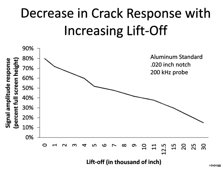
Figura 5.21. Diminuição da Resposta à Trinca com o Aumento do Lift-Off
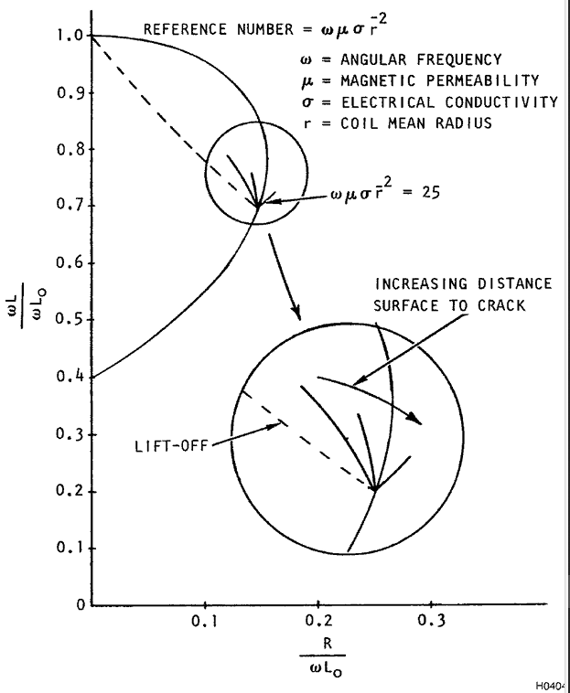
Figure 5.22. Diagrama de Impedância Mostrando o Efeito de uma Trinca
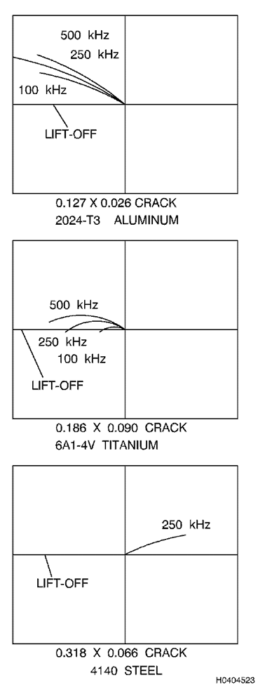
Figura 5.23. Relação de Fase entre Lift-Off e Resposta à Trinca para Vários Materiais e Frequências.
5.23.6
Materiais Ferromagnéticos.
A variabilidade na permeabilidade pode
dificultar a inspeção por correntes parasitas de materiais
ferromagnéticos. A permeabilidade e o lift-off têm aproximadamente a
mesma direção de variação da impedância em materiais ferromagnéticos
não magnetizados, mas pode haver variações muito grandes na
permeabilidade, que são muito difíceis de compensar. A saturação
magnética pode ser usada para superar as dificuldades apresentadas
pelos efeitos da permeabilidade. Nessa técnica, o material é saturado
magneticamente por um campo magnético CC alto. Isso reduz a
permeabilidade para cerca de 1 e a torna constante. Isso resulta em um
material de condutividade relativamente baixa, essencialmente não
ferromagnético, para aplicações de CP.
5.23.7
Discriminação de Fase.
Cada uma das variáveis (lift-off,
condutividade, espessura, permeabilidade e falhas) tem um efeito
característico na impedância líquida de uma bobina. A exibição das
curvas de impedância causadas por alterações nas variáveis de
inspeção pode ser de grande ajuda para determinar a causa de uma
alteração.
5.23.8
Oscilação da Sonda. Ao realizar a inspeção manual por correntes
parasitas com uma sonda de superfície ou sonda tipo lápis, geralmente é
impossível manter a sonda no mesmo ângulo em relação à superfície de
inspeção, à medida que a posição é alterada. Em alguns casos, suportes
podem ser fabricados para guiar a sonda e manter a relação angular com
a superfície de inspeção. A alteração angular entre a sonda e a
superfície de inspeção é denominada oscilação da sonda. A oscilação da
sonda resulta em alterações na elevação, mostradas na Figura 5.24. A
quantidade de elevação obtida devido a alterações no ângulo da sonda
depende do diâmetro e do formato da ponta da sonda. Pontas arredondadas
de sondas de pequeno diâmetro resultam em menor decolagem do que sondas
de ponta plana com diâmetros maiores. Em instrumentos de exibição de
impedância, o efeito de decolagem pode ser reduzido alterando a relação
de ganho vertical para horizontal.
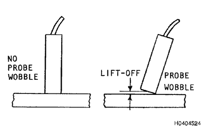
Figura 5..24. Efeito Lift-off Resultante da Oscilação da Sonda (Probe Wobble)
5.24 Efeitos da Localização de Trincas na Detectabilidade.
5.24.1
Localização e Orientação de Trincas.
Informações sobre o histórico de
trincas em locais específicos de inspeção são muito importantes. Ordens
Técnicas de Conformidade de Tempo (TCTO) são frequentemente emitidas
com base em problemas que ocorreram em um ou mais sistemas da aeronave.
Isso significa que há um problema conhecido e que inspeções são
necessárias. A localização precisa de trincas suspeitas e sua
orientação produzem inspeções mais confiáveis. Frequentemente, essas
informações são fornecidas a partir do histórico anterior de trincas
nos locais designados. Em outros casos, essas informações podem ser
determinadas a partir do conhecimento da distribuição de tensões
durante o serviço. A definição mais precisa da localização e orientação
das trincas permite que o inspetor reduza seu tempo de inspeção. Para
inspeção manual por correntes parasitas, a redução no tempo de
varredura proporciona menos fadiga do operador e consequente melhoria
na confiabilidade da inspeção.
5.24.2
Trincas nas Bordas das Peças.
A borda de uma peça pode ser representada
como uma trinca infinitamente grande e, consequentemente, produz um
sinal forte durante a inspeção por correntes parasitas. O problema na
inspeção de trincas nas bordas das peças é a separação da resposta da
trinca da resposta forte da borda (efeito de borda). Ao fixar a
distância da sonda a uma borda, o efeito de borda é minimizado. Guias
de sonda melhoram a capacidade de detecção de trincas nas bordas.
5.24.3
Inspeção nas Bordas das Peças.
Duas abordagens podem ser utilizadas
para inspecionar trincas nas bordas das peças. O primeiro método
consiste em anular o instrumento com a sonda na borda da peça. Em
seguida, geralmente com um dispositivo de fixação não condutor ou algum
outro método, a sonda é mantida na borda enquanto é varrida ao longo
dela. Se essa posição puder ser mantida, a inspeção pode ser realizada
com maior sensibilidade do que seria possível com o mesmo instrumento e
a sonda afastados da borda. A segunda abordagem consiste em utilizar
uma sonda blindada, minimizando assim a resposta das bordas.
5.24.4
Dispositivos de Fixação e Suportes para Inspeção de Bordas.
Um dos
métodos mais simples para inspeção por correntes parasitas adjacentes a
uma borda linear de uma peça é fixar com fita adesiva ou segurar uma
régua a uma distância predeterminada da borda. Réguas não metálicas
DEVEM ser utilizadas para esse propósito. Um dispositivo de fixação
simples que pode auxiliar no posicionamento da sonda adjacente a uma
borda é mostrado na Figura 5.25. Este dispositivo mantém o centro da
sonda a 1/8 de polegada da borda, mas uma inspeção mais próxima da
borda pode ser obtida variando a posição do furo perfurado.
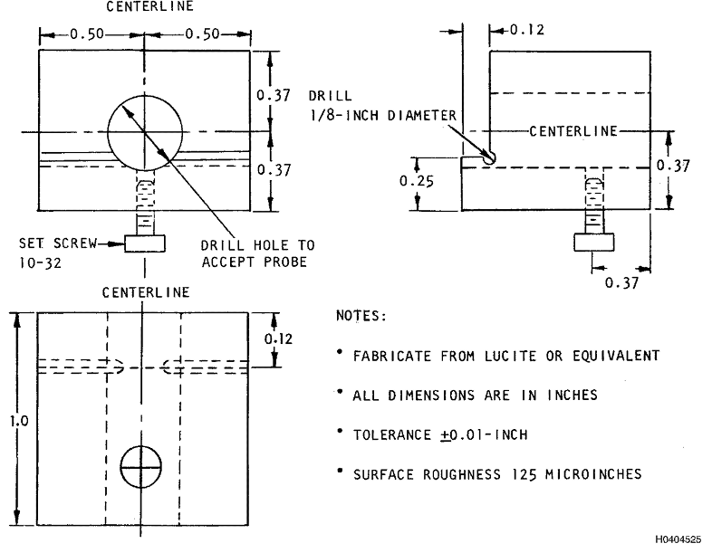
Figura 5.25. Guia de Sonda Para Inspeção em Borda
5.24.5
Curvatura.
Quando sondas tipo lápis de pequeno diâmetro são empregadas,
a curvatura tem efeito mínimo na resposta à trinca. Isso se deve ao
efeito de elevação mínimo do tamanho reduzido da ponta da sonda. Para a
maioria das aplicações que envolvem inspeção de superfícies curvas com
sondas tipo lápis de pequeno diâmetro, padrões planos podem ser usados
satisfatoriamente para superfícies curvas no estabelecimento de
requisitos de sensibilidade.
5.24.6
Detecção de Falhas Subsuperficiais.
Cada vez mais, surgem aplicações
nas quais se deseja inspecionar trincas que se iniciam abaixo de uma
superfície acessível. Isso pode ser uma trinca que se inicia no lado
oposto da superfície acessível, na estrutura em contato com a
superfície oposta de uma superfície acessível ou abaixo de um
revestimento ou revestimento condutor. A CP pode ser uma ferramenta
poderosa para a detecção de falhas subsuperficiais.
5.24.7
Análise do Plano de Impedância de Falhas Subsuperficiais.
Se a
frequência necessária for utilizada com instrumentação de análise de
plano de impedância, é possível obter a penetração de correntes
parasitas na área da falha. As informações de fase e amplitude
recebidas da falha podem ser diretamente relacionadas à profundidade da
falha.
5.24.8
Detecção de Trincas sob Revestimentos Metálicos.
A detecção de trincas
sob revestimentos e chapeamentos metálicos é semelhante à detecção de
falhas subsuperficiais. A magnitude da resposta total diminui
consistentemente com o aumento da espessura do revestimento. Com
instrumentação do tipo medidor com um sistema de teste de frequência
constante, a espessura do chapeamento ou revestimento através da qual
as trincas podem ser detectadas diminui com o aumento da condutividade
do chapeamento e da permeabilidade magnética. Em geral, a diminuição da
frequência permite a detecção de trincas maiores sob revestimentos mais
espessos devido à maior profundidade de penetração. A detecção de
trincas sob revestimentos metálicos com instrumentação de análise de
fase usando o diagrama do plano de impedância pode ser realizada com
mais precisão e sensibilidade do que com instrumentos medidores, pois
as informações de fase podem ser medidas. Pesquisas recentes mostraram
que sistemas de correntes parasitas multifrequenciais podem ser
aplicados para detectar e medir trincas sob revestimentos metálicos.
5.25 Efeitos das Técnicas de Varredura na Detecção.
5.25.1
Técnica de Inspeção.
O posicionamento consistente da sonda em relação
às bordas e interfaces durante a configuração e a varredura deve ser
estabelecido para garantir a máxima resposta a falhas com o mínimo de
interferência de outras fontes de indicações. Se houver condições que
possam resultar em indicações falsas ou que possam mascarar indicações
verdadeiras de falhas, essas condições DEVEM ser observadas no
procedimento e um meio de interpretar ou avaliar as indicações falsas
deve ser fornecido. Ao realizar a inspeção por correntes parasitas de
uma área, a distância entre as varreduras ou entre as medições deve ser
selecionada para garantir a cobertura completa da falha de tamanho
mínimo ou variação nas propriedades a serem detectadas. Ao determinar a
distância máxima entre as varreduras, deve-se considerar a mudança na
magnitude da resposta à falha à medida que a posição central da bobina
da sonda aumenta em distância do centro da trinca.
5.25.2
Velocidade de Varredura.
A velocidade de varredura usada na CP para
trincas está relacionada ao tipo de equipamento e à técnica de inspeção
utilizada. Velocidades de varredura mais lentas são necessárias quando
o inspetor precisa interpretar a leitura enquanto direciona manualmente
a sonda no padrão de varredura especificado. No entanto, se o filtro
passa-alto (HPF) for utilizado durante o processo de inspeção, a
velocidade de varredura consistente é fundamental para garantir que a
resposta do sinal recebida para uma falha seja precisa. O HPF pode
diminuir a resposta do sinal se a velocidade de varredura for reduzida
durante o processo de avaliação em relação à velocidade usada durante a
padronização inicial. Quanto maior o HPF, mais drástica será a mudança
na resposta do sinal quando a velocidade de varredura for reduzida
(Figura 5.26).
5.25.3 Forma de Varredura.
O padrão de varredura necessário para a CP
baseia-se no possível local de início da trinca, na orientação das
trincas e no tamanho das trincas que devem ser detectadas. Se as
trincas se iniciarem a partir de uma borda em material fino
(aproximadamente 0,050 polegada), a inspeção por correntes parasitas
geralmente se limita a uma única varredura da borda. Para materiais
mais espessos, varreduras podem ser necessárias em ambas as superfícies
adjacentes à borda e uma ou mais varreduras do material entre as
bordas. Quando as trincas se iniciam abaixo das cabeças de fixadores
não removíveis, o padrão geralmente consiste em uma única varredura ao
redor da cabeça saliente do fixador para detectar trincas que crescem
para fora do furo. Se as trincas podem ocorrer em uma variedade de
posições e orientações, como é possível em superfícies planas, em raios
e em superfícies cilíndricas, a varredura deve ser realizada de forma a
garantir a detecção das menores trincas necessárias. Para esses tipos
de áreas de inspeção, a direção da varredura, o número de varreduras e
a distância entre elas DEVEM ser especificados.
5.25.4
Equipamentos Automáticos ou Semiautomáticos.
Equipamentos automáticos
de correntes parasitas, em conjunto com registradores de alta
velocidade, são capazes de operar em velocidades extremamente altas. Os
limites superiores da velocidade de varredura são baseados na
frequência operacional e nas taxas de amostragem do registrador ou do
leitor. O principal uso de equipamentos automatizados de correntes
parasitas pelos militares é a inspeção de furos de parafusos. Nesta
aplicação, velocidades de rotação de 40 a 3.000 rpm podem ser obtidas
pelo sistema de inspeção.
5.25.5
Uso de Registradores ou Mostradores Digitais.
O uso de registradores ou
mostradores digitais (instrumentos de correntes parasitas do tipo LCD)
permite aumentar a velocidade da varredura manual até os limites
impostos pelo tempo de reação desses instrumentos. Geralmente, outras
restrições relacionadas à orientação da sonda no padrão de varredura
prescrito tornam-se o fator de controle quando registradores ou
mostradores digitais são usados.
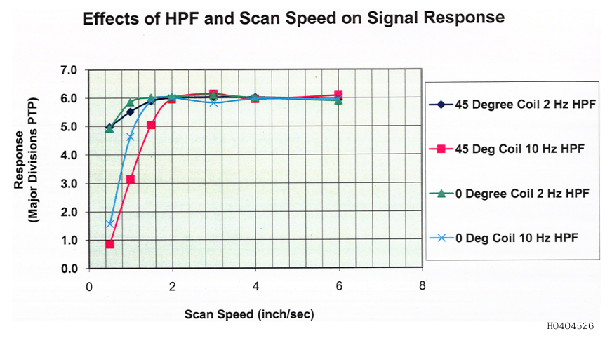
Figura 5.26. Efeito da Velocidade de Varredura na Resposta a uma Trinca Usando Bobinas "Ribbon "
5.26 Padrões de Referência para Trincas
CUIDADO:
Padrões
de referência de correntes parasitas de uso geral em aço, como a
maioria dos materiais ferromagnéticos, são suscetíveis à corrosão se
não forem armazenados corretamente. Corrosão inferior a 0,010”
(Profundidade de Pites) não afeta a capacidade de manutenção do padrão
e pode ser tratada com uma lixa (por exemplo, Scotch-Brite ou
equivalente) para remover a corrosão da superfície. Padrões de aço com
corrosão superior a 0,010” (Profundidade de Pites) são inutilizáveis
e devem ser substituídos antes de serem usados novamente. O padrão
de aço deve ser revestido com óleo leve e protegido contra intempéries
(por exemplo, saco plástico, caixa plástica, etc.) quando não estiver
em uso.
Existem
diversos materiais sob inspeção no Departamento de Defesa. Um inspetor
encontrará dois padrões principais de correntes parasitas de uso geral
para alumínio em campo: o padrão da Força Aérea, NSN 6635-01-092-5129,
P/N 7947479-10 (alumínio) e o padrão da Marinha, PN NRK-3A (alumínio).
O padrão de alumínio da Marinha possui uma placa inferior de maior
condutividade. A Marinha também possui um kit composto por três padrões
com a mesma configuração geométrica, cada um de um material diferente
(kit PN NRK-3AST, NSN 5280-01-352-1336). Este kit consiste em:
- Um
padrão de alumínio, P/N: NRK-3A ou NRK-3AL, é feito de camadas superior
e intermediária 7075-T651 e uma camada inferior 7075-T73
- Um padrão de aço, P/N: NRK-3S ou NRK-3ST, é feito de liga 4340 em todas as três camadas
- Um padrão de titânio, P/N: NRK-3T ou NRK-3TI, é feito de 6AL4V, é uma liga em todas as três camadas
NOTA
A
menos que especificado de outra forma pela autoridade de engenharia de
sistemas de armas, o padrão de correntes parasitas de uso geral da
Força Aérea (Figura 5.29 (Folha 1) até a Figura 5.29 (Folha 3)) DEVERÁ
ser o padrão comum usado para executar CP em componentes de alumínio
dentro da Força Aérea. O padrão feito para a configuração da Marinha
(Figura 4-56) pode ser usado como um substituto para o padrão de
correntes parasitas de uso geral da Força Aérea. Ao usar o padrão da
Marinha, calibre nos entalhes longos do EDM para inspeções de
superfície e nos entalhes de canto nas camadas superiores para
inspeções de furos de parafusos, a menos que seja instruído de outra
forma por um procedimento específico da peça.
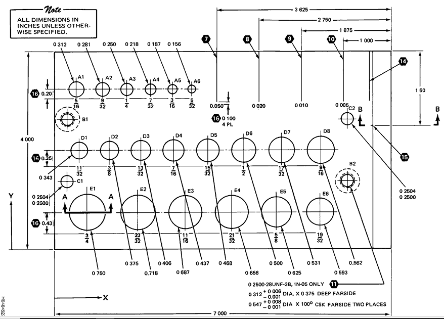
Figura 5.27. Padrão de correntes parasitas de uso geral da Força Aérea (Folha 1 de 3)
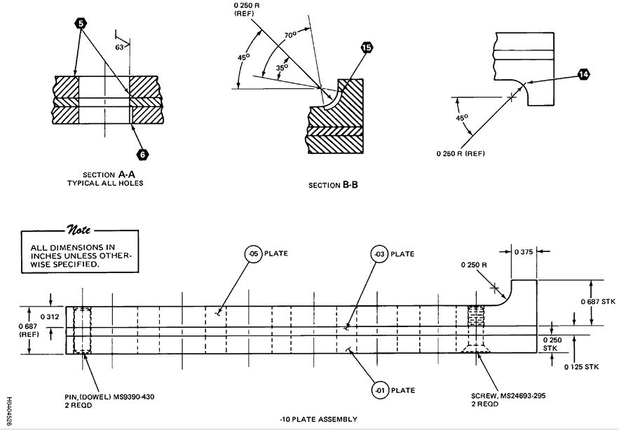
Figura 5.28. Padrão de correntes parasitas de uso geral da Força Aérea (Folha 2)
Figura 5.29. Padrão de correntes parasitas de uso geral da Força Aérea (Folha 3)
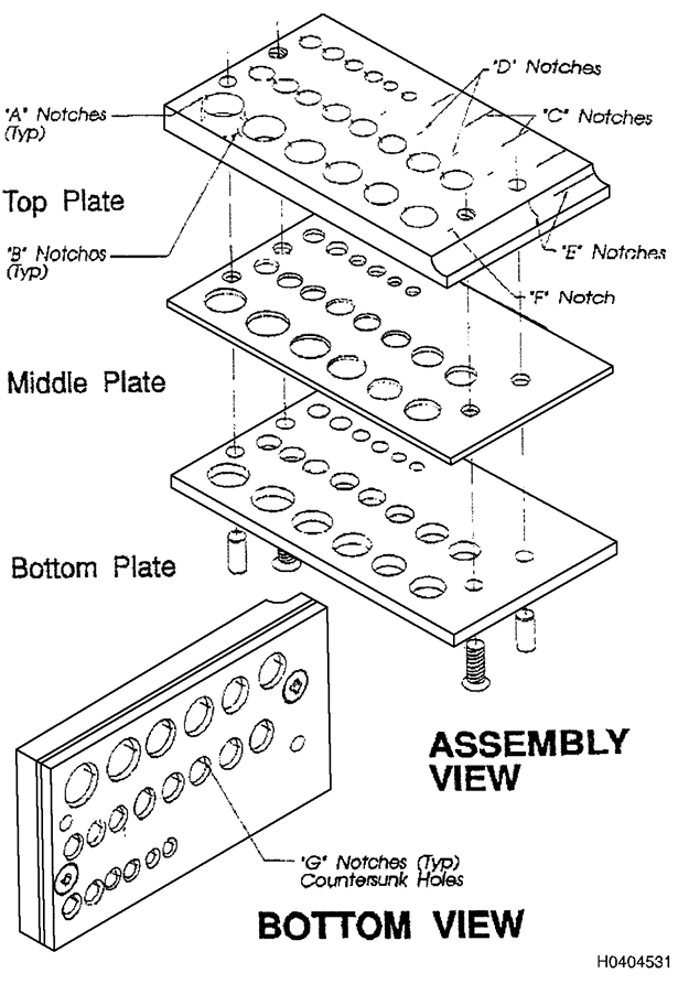
Figura 5.30. Padrão de referência de correntes parasitas da Marinha (Folha 1 de 2)
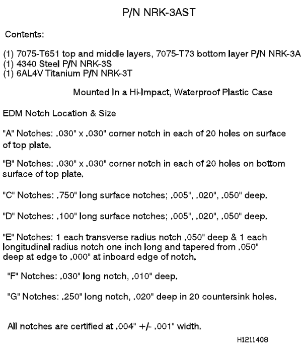
Figura 5.31. Norma de Referência para Correntes parasitas da Marinha (Folha 2)
5.26.1
Trincas como Padrões de Referência.
Quando um instrumento de correntes
parasitas é configurado para detecção de trincas, alguns meios devem
ser fornecidos para garantir que a sensibilidade do sistema de teste
seja suficiente para detectar o menor tamanho de trinca necessário.
Idealmente, o melhor padrão seria uma seção do mesmo material contendo
uma trinca desse tamanho mínimo. Trincas de tamanhos especificados são
difíceis de obter. Com poucos espécimes para escolher, tais situações
são raras. Trincas de fadiga de tamanho especificado podem ser
cultivadas em condições de laboratório, mas esse método é extremamente
caro. O comprimento da trinca ao longo da superfície e sua largura na
superfície são facilmente mensuráveis. A profundidade da trinca é
geralmente desconhecida e deve ser aproximada a partir de outros dados.
Devido à dificuldade em obter trincas reais para padrões de referência,
vários outros padrões podem ser usados. Esses padrões são discutidos
abaixo.
5.26.2
Requisitos para Padrões de Referência.
O principal requisito para
padrões de referência de correntes parasitas é que eles forneçam
uniformidade de resposta que possa ser correlacionada à condição ou
propriedade do material a ser detectada ou medida. Duas ideias
fundamentais são assumidas pela uniformidade de resposta. Primeiro,
isso significa que todos os ensaios podem ser realizados com a mesma
sensibilidade ou que diferentes níveis de sensibilidade podem ser
comparados quantitativamente. Segundo, os padrões fabricados para um
projeto específico devem ser dispositivos estáveis, capazes de fornecer
uma resposta repetível dentro de certos limites especificados. Para ser
útil na avaliação do tamanho e tipo da falha, o padrão de referência
deve estar relacionado à falha a ser detectada. Por meio de dados de
correlação, histórico ou investigação prévia, a resposta do padrão de
referência deve estar relacionada à resposta da condição ou propriedade
do material da peça. Para permitir a fabricação de padrões em diversos
locais, as tolerâncias de material, liga, têmpera e dimensões que
fornecerão a resposta necessária devem ser definidas na ordem técnica
aplicável ao ensaio a ser realizado. Métodos de fabricação que utilizam
ferramentas simples DEVEM ser especificados quando uniformidade e
sensibilidade adequadas puderem ser obtidas. Idealmente, quando um
instrumento tiver sido ajustado para uma resposta específica do padrão,
um sinal de aproximadamente a mesma amplitude e fase (quando aplicável)
deve ser obtido da condição ou propriedade do material com um
instrumento de correntes parasitas e sonda do mesmo tipo geral.
5.26.3
Padrões para Ensaios Específicos.
Os padrões devem ser projetados para a
propriedade ou condição específica do material que está sendo ensaiado.
Padrões específicos são necessários para cada tipo de teste que está
sendo realizado. Os padrões de calibração usados para classificar
ligas devem atender a requisitos de condutividade muito específicos. Os
padrões de calibração para medir a espessura do revestimento de
revestimentos condutores não seriam adequados para medir a espessura do
revestimento de tinta ou outros revestimentos não condutores ou para
detectar rachaduras ao redor de furos de rebites. Furos perfurados ou
entalhes de EDM (usinagem por eletrodescarga) em um bloco de alumínio
não devem ser usados para testar a espessura do material ou a
composição da liga de peças de titânio ou aço inoxidável.
5.26.4
Defeitos Artificiais para Padrões.
Devido à dificuldade de obter os
tipos e tamanhos de defeitos reais em peças para uso como padrões de
referência, uma variedade de defeitos artificiais foi desenvolvida para
simular os defeitos reais. Trincas por fadiga foram cultivadas em
condições de laboratório, mas tamanhos reproduzíveis em quantidade
suficiente para padrões são impraticáveis. Defeitos artificiais, como
furos perfurados, entalhes por eletroerosão, cortes de serra, duas
superfícies fixadas para simular uma trinca ou condições produzidas
quimicamente para simular pites ou corrosão, podem ser produzidos de
diversas maneiras. Idealmente, um defeito artificial produzirá uma
resposta de correntes parasitas idêntica à resposta de um defeito real
do mesmo tamanho, orientação e localização. Esse ideal raramente é
alcançado com defeitos artificiais. A estimativa do tamanho do defeito
a partir da resposta a defeitos artificiais deve ser baseada na
correlação de tamanhos de defeitos previamente conhecidos com a
resposta dos defeitos artificiais. Para manter a qualidade dessa
correlação, é necessário especificar cuidadosamente as propriedades do
material e o processo de fabricação do padrão de defeito artificial.
5.26.5
Condições Simuladas para Padrões.
Ao utilizar técnicas de correntes
parasitas para medir condutividade, espessura de revestimento,
permeabilidade, classificação de ligas e dureza, geralmente é possível
obter padrões que representam os materiais e as condições que estão
sendo testados. Esses padrões de calibração são usados para
comparação direta com a resposta observada na peça que está sendo
ensaiada. Muito cuidado deve ser tomado ao manusear esses tipos de
padrões de calibração. Arranhões, amassados, distorções, oxidação ou
outras condições podem alterar os padrões de calibração, tornando-os
inúteis para fins de comparação e calibração. Os padrões primários
geralmente são mantidos em condições de armazenamento em laboratório e
podem ser rastreáveis até o Instituto Nacional de Padrões e
Tecnologia (NIST). O padrão secundário é comparado ao padrão primário
para resposta; os padrões secundários são considerados rastreáveis
até o padrão primário. Os ensaios reais em campo utilizam os padrões
secundários (ou terciários), e os padrões são comparados periodicamente
ao padrão primário para garantir sua integridade.
5.26.6
Entalhes Usinados por Eletroerosão (EDM).
Entalhes usinados por descarga elétrica (EDM=Electro Discharge Machine), em uma
variedade de tamanhos, formas e localizações, podem ser colocados em
quase todos os metais. A largura do entalhe pode ser mantida em até
0,003 polegadas e, embora muito maior em largura do que a maioria das
trincas, este método fornece uma ranhura, ou entalhe, mais estreita do
que todas as outras técnicas de fabricação, como cortes de serra.
Respostas semelhantes são obtidas em trincas reais.
5.26.7 Entalhes
por EDM em Aço Ferromagnético. O sinal de corrente parasita não penetra
bem em materiais ferromagnéticos devido ao efeito de blindagem da alta
permeabilidade magnética. Entalhes por EDM são úteis como exemplos de
falhas abertas na superfície de uma peça. Trincas de ruptura da
superfície são melhor detectadas usando uma frequência muito alta (500
kHz ou mais), que não deve penetrar profundamente na peça. Sob essas
condições, o teste fornece sensibilidade muito alta a falhas
superficiais em materiais ferromagnéticos. Da mesma forma, o teste
fornece pouca ou nenhuma informação sobre a profundidade da falha.
5.26.8
Entalhes de Serra.
Provavelmente, o método mais simples de preparar
padrões de correntes parasitas é por meio de uma serra de joalheiro.
Com uma lâmina 7/0, entalhes tão estreitos quanto 0,007 a 0,008
polegadas podem ser feitos na borda de um padrão. Serras circulares de
joalheiro também estão disponíveis para outros locais de entalhe. A
resposta de fase é semelhante à obtida a partir de trincas. No entanto,
à medida que a largura do entalhe aumenta, a semelhança com uma trinca
diminui.
5.26.9
Entalhes Usinados.
Padrões com entalhes usinados podem ser usados em
algumas condições de ensaio. No entanto, a resposta de um determinado
tamanho e frequência de sonda ao entalhe deve ser avaliada quanto à sua
aplicabilidade a uma situação de ensaio.
5.26.10
Escolha de Padrões de Referência para Trincas.
Como discutido
anteriormente, o principal requisito para padrões de referência de
correntes parasitas é que eles forneçam uniformidade de resposta que
pode ser relacionada ao tamanho mínimo da trinca a ser detectada. Em
vários graus, vários tipos de padrões de referência podem atender a
esse critério. Consequentemente, fatores como custo, facilidade de
fabricação, disponibilidade e aplicação em campo tornam-se
considerações primordiais.
5.27 Medição de Espessura.
5.27.1 Critérios para Aplicação.
5.27.2
Tipos de Medições.
Em geral, três tipos de medições de espessura podem
ser realizadas por técnicas de correntes parasitas. A espessura total
de produtos metálicos finos, como folhas, tiras e folhas, pode ser
determinada quando a dimensão da espessura é menor que a profundidade
efetiva de penetração das correntes parasitas no material. Uma segunda
categoria de medição de espessura inclui a medição de galvanoplastia ou
revestimento metálico em uma base condutiva ou magnética. Subcategorias
de medições de galvanoplastia e revestimento podem ser estabelecidas
com base na condutividade ou permeabilidade relativa da galvanoplastia
e do metal base sobre o qual é galvanizada. Subcategorias típicas de
medições de galvanoplastia incluem o seguinte:
- Revestimento de baixa condutividade em base de alta condutividade
- Revestimento de alta condutividade em base de baixa condutividade
- Revestimento de baixa permeabilidade em uma base de alta permeabilidade
- Revestimento de alta permeabilidade em uma base de baixa permeabilidade
5.27.3
Os termos alto e baixo são relativos e não se destinam a indicar
valores específicos. A terceira categoria de medição é a determinação
da espessura de revestimentos não condutores em uma base metálica. Esta
aplicação também pode ser estendida para medir a espessura total de
materiais finos não condutores acessíveis de ambos os lados, segurando
um bloco de metal contra a superfície oposta à sonda.
5.27.4
Limitações Gerais da Medição da Espessura de Revestimentos.
O uso de
técnicas de correntes parasitas para medição de espessura é restrito a
materiais finos. Essa limitação resulta da incapacidade do campo de
correntes parasitas de penetrar profundamente em materiais condutores.
A profundidade efetiva de penetração e, portanto, a espessura que pode
ser medida, diminui à medida que a condutividade e/ou a permeabilidade
do metal aumenta. Para determinar a espessura de revestimentos ou
revestimentos em substratos metálicos, deve haver uma diferença na
condutividade ou permeabilidade entre o material da superfície e o
material da base. Obtém-se maior sensibilidade à medida que as
diferenças entre a condutividade ou permeabilidade do revestimento e do
substrato se tornam maiores. Para revestimentos não condutores, a
sensibilidade melhora com o aumento da frequência. Sondas de diâmetros
maiores proporcionam maior sensibilidade para medição de revestimentos
mais espessos. Um resumo dos efeitos de um aumento nas propriedades do
material e nas variáveis de inspeção sobre a sensibilidade e a faixa
de medições de espessura é apresentado na Tabela 8-8, na Seção 8.
5.27.5
Sistemas de Ensaio.
Uma grande variedade de equipamentos especializados
é fabricada para medição de espessura. Muitos desses instrumentos são
otimizados para um ou dois tipos de aplicações. Exemplos incluem
instrumentos projetados para medir revestimentos não condutores em
metais não magnéticos ou instrumentos para medir revestimentos não
magnéticos em um substrato magnético. Devido a requisitos limitados,
tais equipamentos especializados geralmente não estão disponíveis para
uso em campo. Na maioria dos casos, instrumentos de uso geral podem ser
adaptados para medição de espessura. Muitos dos instrumentos do tipo
medidor podem ser usados para uma ampla variedade de operações de
medição de espessura. Equipamentos de análise de plano de impedância
são muito úteis para medição de espessura. A mudança de fase é quase
linear com o aumento da profundidade de penetração, proporcionando
assim sensibilidade e precisão mais consistentes em toda a faixa de
medição.
5.27.6
Procedimentos de Medição de Espessura.
Antes que a medição de espessura
possa ser realizada, os procedimentos de medição por correntes
parasitas DEVEM ser cuidadosamente estabelecidos e comprovados para
garantir precisão e confiabilidade. As curvas DEVEM ser preparadas para
relacionar as leituras do instrumento aos padrões de espessura
conhecidos. Um número suficiente de amostras dentro da faixa de
espessura a ser medida deve ser usado na preparação das curvas para
garantir que uma curva suavemente crescente ou decrescente seja obtida.
O tipo e o número de padrões necessários para a padronização do
instrumento DEVEM ser definidos. As limitações dos procedimentos em
termos de aplicabilidade de material e dimensão DEVEM ser estabelecidas
e observadas nos procedimentos.
5.28 Medição da Espessura Total do Metal.
5.28.1
Aplicações da Medição da Espessura Total.
O principal uso das técnicas
de correntes parasitas para medir a espessura total de peças metálicas
é detectar corrosão nas laterais ou entre camadas da estrutura. No
entanto, essa técnica também pode ser usada para estabelecer a
espessura de uma chapa fina, determinar desgaste ou afinamento de
materiais da chapa e medir espessura, erosão ou corrosão de paredes de
tubos. A medição de espessura com CP é geralmente usada quando:
- paquímetros ou outras medidas mecânicas são impraticáveis
- equipamento ultrassônico não está disponível
- se materiais muito finos devem ser medidos
5.28.2
Limitações da Espessura Total.
A precisão e a faixa de espessura do
metal medidas com CP dependem das propriedades eletromagnéticas do
material e do sistema de ensaio. O aumento da condutividade e da
permeabilidade magnética aumenta a precisão na medição de amostras
muito finas, mas diminui a faixa efetiva de medição e a precisão em
profundidades maiores. Portanto, em uma frequência especificada, é
possível medir metais mais espessos que apresentam baixa condutividade
e/ou baixa permeabilidade magnética em comparação com metais que
apresentam alta condutividade e/ou alta permeabilidade.
5.28.3
Efeitos da Frequência na Medição da Espessura Total.
Assim como a
diminuição da frequência aumenta a profundidade de penetração das
correntes parasitas em um condutor, a diminuição da frequência também
aumenta a espessura de um metal que pode ser medida por técnicas de CP.
Maior sensibilidade é obtida para as amostras mais finas com uma
frequência mais alta. Para espessuras (acima de 0,050 polegada), a
frequência mais baixa proporciona maior sensibilidade e maior
penetração geral. A sensibilidade em qualquer faixa de espessura pode
ser determinada pela inclinação da linha de espessura plotada: quanto
maior a inclinação (ordenada sobre a abcissa), melhor a sensibilidade.
A frequência ideal pode ser estimada usando a fórmula para uma
profundidade de penetração padrão.
5.28.4
Efeitos da Construção da Sonda.
Sondas projetadas especificamente para
medição de espessura possuem núcleos de ar e geralmente são maiores em
diâmetro do que as sondas com núcleo de ferrite usadas para detecção de
falhas. Sondas com diâmetro maior realizam a média das medições de
espessura em uma área maior. Sondas com diâmetro menor e sondas com
núcleo de ferrite reduzem a área de medição e, portanto, podem ser
usadas em áreas menores e mais próximas das bordas. As sondas com
núcleo de ar maiores podem fornecer maior sensibilidade para medições
de espessura do que as sondas com núcleo de ferrite em formato de lápis.
5.28.5
Procedimentos Operacionais para Medição de Espessura Total.
Todas as
medições de espessura DEVEM ser realizadas de acordo com procedimentos
pré-estabelecidos. Em geral, esses procedimentos incluirão as seguintes
etapas:
- a) Prepare a peça para medição de espessura.
- b) Estabelecer a presença de fatores geométricos que limitem ou restrinjam a medição da espessura.
- c) Selecione o sistema de teste, a sonda e a frequência operacional apropriados.
- d)
Desenvolver ou verificar uma curva de calibração usando padrões de
calibração rastreáveis do NIST ou usando padrões de referência de
espessura conhecidos para configurar o sistema de teste.
- e) Realizar medições de espessura em pontos designados.
- f) Registre a espessura e informe todos os valores rejeitáveis, conforme exigido pelo procedimento escrito.
NOTA
Ao
medir espessura usando CP, certifique-se de que a sonda e a peça a ser
medida estejam suficientemente afastadas de qualquer outro metal para
que as correntes parasitas não sejam afetadas. Acessórios metálicos em
chapas metálicas devem ser evitados devido à interferência
condutiva.
5.28.6
Preparar a peça para medição de espessura.
Muitas medições de espessura
devem ser realizadas por meio de revestimentos não condutores, como
tinta ou revestimentos anódicos. A compensação de elevação deve ser
usada durante a calibração. Qualquer material estranho solto DEVE ser
removido da superfície onde a espessura está sendo determinada.
Quaisquer arestas vivas, saliências ou produtos químicos que sejam
potencialmente prejudiciais à sonda DEVEM ser removidos.
5.28.7
Presença de limitações geométricas.
Antes de medir espessura por
técnicas de correntes parasitas, deve-se estabelecer a presença e a
posição de quaisquer características estruturais que possam restringir
a acessibilidade ou reduzir a precisão da medição. A medição de
espessura deve ser realizada suficientemente longe de fixadores e
outros objetos condutores para evitar que influencie a leitura do
medidor. O acesso limitado pode restringir o tipo de sonda a ser usada.
Na maioria dos casos, os procedimentos de inspeção por escrito
definirão as limitações geométricas.
5.28.8
Seleção do Sistema de Ensaio.
O sistema de teste selecionado para
medição de espessura deve ser baseado nos requisitos de medição de
espessura, na frequência do instrumento de correntes parasitas e nos
tipos de sondas disponíveis.
5.28.9
Seleção da Frequência de Teste para Medição de Espessura.
Para cada
tarefa de medição de espessura a ser realizada por técnicas de
correntes parasitas, há uma frequência ou faixa de frequências ideal
que proporcionará sensibilidade ideal na profundidade a ser medida. O
produto da condutividade do material em porcentagem IACS e a
permeabilidade magnética relativa é plotado ao longo do eixo vertical,
e a frequência em quilohertz é plotada ao longo do eixo horizontal. As
linhas que representam as espessuras ideais são plotadas no gráfico.
Para determinar a frequência recomendada, o produto da condutividade do
material e da permeabilidade relativa do material a ser medido é
encontrado no eixo vertical. Siga este ponto horizontalmente até a
linha diagonal que representa a espessura a ser medida. A frequência
recomendada é encontrada no eixo horizontal estendendo uma linha
verticalmente para baixo a partir do ponto estabelecido. Uma variação
considerável deste valor de frequência ainda fornecerá sensibilidade
suficiente para a maioria das espessuras.
5.28.10
Configuração do Instrumento.
Como os instrumentos de uso geral não são
projetados especificamente para medição de espessura, deve-se
estabelecer uma correlação entre as leituras do instrumento e as
dimensões da espessura. Portanto, as faixas de espessura nas quais as
medições devem ser realizadas DEVEM ser definidas o mais próximo
possível para minimizar o número de pontos de dados a serem
estabelecidos. Quando aplicável, a compensação do lift-off deve ser
usada para minimizar os efeitos das variações no acabamento da
superfície nas leituras de espessura.
5.28.11
Registrar a Espessura e Relate os Valores Rejeitáveis.
A maioria dos
procedimentos escritos fornece limites de aceitação para a dimensão da
espessura. Quando um valor rejeitável é obtido, é aconselhável
verificar novamente o instrumento usando os padrões de referência ou
calibração. O procedimento escrito geralmente fornece métodos para
relatar valores rejeitáveis.
5.28.12
Padrões para Medição de Espessura Total.
Os padrões usados para
configuração da medição de espessura devem ter a mesma condutividade
elétrica, permeabilidade magnética e geometria do material a ser
medido. A mesma condutividade elétrica geralmente é obtida exigindo que
os padrões sejam fabricados com a mesma liga e têmpera do material de
inspeção. Em materiais magnéticos, a permeabilidade pode variar a tal
ponto dentro de uma única liga e tratamento térmico que a seleção de
padrões
representativos pode ser difícil. A alta permeabilidade do ferro e do
aço ferromagnético restringe o uso da medição de espessura por
correntes parasitas a metais muito finos. A curvatura dos padrões DEVE
ser a mesma da peça a ser inspecionada. Todos os padrões DEVEM ter
espessura uniforme e a precisão da espessura padrão DEVE ser pelo menos
10 vezes maior que a necessária para a precisão da medição da
espessura. Por exemplo, se a medição da espessura for necessária com
precisão de 0,03 mm, os padrões DEVEM ter precisão de 0,003 mm. Todos
os padrões DEVEM ser claramente identificados com liga, tratamento
térmico e espessura.
5.28.13
Precisão da Medição de Espessura. A precisão obtida na medição da
espessura do metal varia amplamente dependendo das propriedades do
material, espessura, frequências utilizadas e nível de ruído do
sistema. Com frequências mais altas (500 kHz e superiores) em materiais
finos (0,25 polegadas e menos), as espessuras podem ser medidas com
precisão de 0,003 polegada. À medida que as frequências diminuem e as
espessuras aumentam, a precisão diminui. Para máxima precisão, as
variações no lift-off, condutividade, geometria e permeabilidade
magnética devem ser reduzidas ao menor nível possível.
5.29
Aplicação da Medição de Revestimentos Condutivos.
Técnicas de CP são
comumente usadas para medir a espessura de revestimentos condutores em
materiais metálicos. Essas medições podem ser usadas como um controle
de processo para determinar a espessura adequada do revestimento ou dos
revestimentos condutores aplicados a um substrato. O afinamento desses
revestimentos e pinturas, devido à erosão ou corrosão, também pode
ser estabelecido. A CP é algumas vezes usada para determinar a presença
e a espessura de camadas superficiais cuja composição foi alterada pelo
metal mais profundo na peça. Essa aplicação inclui a medição de camadas
cementadas em aço e a profundidade da contaminação por oxigênio ou
hidrogênio das camadas superficiais de ligas de titânio. A absorção de
carbono nas camadas superficiais do aço reduz efetivamente a
permeabilidade magnética. A solução de hidrogênio e oxigênio na
superfície da liga de titânio reduz a condutividade da superfície. A
quantidade de contaminação superficial pode ser medida medindo-se as
mudanças na permeabilidade e na condutividade.
5.29.1 Efeito das Propriedades do Material nas Medições de Espessura de Revestimento.
Embora a profundidade de penetração de correntes parasitas em metais
diminua com o aumento da condutividade elétrica, a falta de penetração
para medir a espessura do revestimento raramente é um problema. As
espessuras de revestimento e pinturas raramente excedem 0,13-0,25 mm e, em muitos casos, são menores que 0,08 mm de
espessura. A sensibilidade da inspeção é controlada em grande medida
pela diferença na condutividade e/ou permeabilidade magnética entre o
metal base e o revestimento. A medição da espessura do revestimento ou
pintura é considerada viável se o produto da condutividade e da
permeabilidade para o metal base e o revestimento tiver uma razão de
1,5 ou maior ou 0,67 ou menor. A sensibilidade aumenta à medida que a
diferença no valor da condutividade ou da permeabilidade entre o
revestimento e o substrato aumenta. Portanto, uma determinação
aproximada da sensibilidade pode ser obtida a partir de uma curva de
impedância, que mostra as posições dos substratos e do revestimento na
frequência e no tamanho da sonda usados para inspeção.
5.29.2 Efeito das Condições de Teste na Medição da Espessura da Deposição.
Normalmente, as frequências utilizadas para a medição da espessura da
deposição são relativamente altas, de 100 kHz ou mais em equipamentos
especializados; frequências de até 6 MHz estão disponíveis. Essas
frequências proporcionam alta sensibilidade para revestimentos muito
finos. À medida que as diferenças de condutividade entre a deposição e
o metal base diminuem, a frequência pode ser aumentada ou diminuída,
conforme necessário, para obter uma sensibilidade equivalente para a
espessura a ser medida. Uma liberdade de escolha considerável a partir desses
valores aproximados pode ser utilizada na escolha da frequência
operacional real. Em caso de dúvida, uma curva de calibração de ensaio
deve ser preparada. Para reduzir os efeitos da rugosidade da superfície
e das variações em revestimentos não condutores, a compensação de
lift-off (técnica de camada intermediária) DEVE ser utilizada.
Geralmente, uma compensação de lift-off de 0,05 a 0,08 mm é
suficiente, a menos que superfícies muito rugosas estejam presentes na
área de ensaio. O aumento do diâmetro da sonda e o uso de núcleos de ar
em vez de núcleos de ferrite aumentam a sensibilidade da medição e
estendem a profundidade na qual a medição precisa da espessura do
revestimento pode ser realizada.
5.29.3
Procedimentos para Medição da Espessura do Revestimento.
Um
procedimento escrito aprovado é necessário para cada aplicação de
técnicas de CP para medição da espessura do revestimento. Cada
procedimento DEVE incluir as seguintes etapas:
- a)
Defina o objetivo da medição da espessura do revestimento ou
galvanoplastia. O tipo de metal base e o revestimento DEVEM ser
incluídos no procedimento.
- b)
Limpe qualquer material estranho da área de inspeção. Mesmo que a
compensação de lift-off seja utilizada, o acúmulo excessivo de material
estranho além do ajuste de lift-off pode levar a erros significativos.
- c) Selecione o sistema de ensaio, a instrumentação e a sonda que realizarão a medição de espessura com a precisão necessária.
- d)
Desenvolver ou verificar a curva de calibração e padronizar o sistema
de ensaio usando os padrões especificados. Uma curva de calibração deve
estar disponível para cada combinação de instrumento e sonda.
- e)
Realize medições da espessura do revestimento nos pontos designados.
Pelo menos três leituras DEVEM ser realizadas em cada posição de
medição para garantir valores precisos e repetíveis. A sonda deve ser
mantida contra a peça com pressão constante (quando disponíveis, sondas
com mola podem ser usadas para auxiliar na manutenção da pressão
constante). Para superfícies curvas, um dispositivo de fixação pode ser
usado para manter a sonda perpendicular à superfície. As medições da
espessura do revestimento DEVEM ser feitas em áreas onde as leituras
não sejam afetadas por estruturas adjacentes, bordas ou variações na
espessura total do revestimento e do substrato que estejam dentro do
limite efetivo de penetração.
- f)
A calibração do instrumento DEVE ser verificada periodicamente em
relação aos padrões para evitar desvios do instrumento.
- g) Verifique
todos os valores medidos em relação às tolerâncias especificadas pelo
procedimento escrito. Todos os valores anormais DEVEM ser relatados
conforme exigido pelo procedimento.
5.29.4
Padrões de Referência para Espessura de Revestimento.
Os padrões de
referência para medições de espessura de revestimento devem ter a mesma
condutividade elétrica, permeabilidade magnética e geometria da peça.
Esses requisitos se aplicam tanto ao material de base quanto ao
revestimento. A condutividade elétrica e a permeabilidade magnética do
material de base são geralmente obtidas usando a mesma liga e tratamento térmico
para os padrões usados na peça. Cuidado especial DEVE ser tomado no
processamento dos materiais para garantir que propriedades semelhantes
sejam obtidas. Os acabamentos superficiais da peça e do padrão DEVEM
ser semelhantes. Para obter a mesma condutividade elétrica,
propriedades magnéticas e acabamento superficial para o revestimento
nas peças e nos padrões de referência, o revestimento deve ser
realizado em banhos de composição semelhante e submetidos a controles
semelhantes. Se o revestimento da peça for aliviado de tensões antes da
medição da espessura, as referências DEVEM receber o mesmo tratamento.
Vários métodos para determinar a espessura do revestimento em padrões
de referência podem ser usados. Um deles é medir cuidadosamente a
espessura antes do revestimento e novamente após o revestimento. A
diferença representa a espessura do revestimento aplicado em apenas um
lado. Um segundo método consiste em medir o revestimento em uma área
adjacente, seccionando uma amostra metalográfica. A espessura total do
revestimento mais o substrato deve exceder a profundidade efetiva de
penetração na peça. Uma espessura total de 2,5 a 3 profundidades de
penetração padrão combinadas é geralmente considerada suficientemente
espessa. Essa espessura pode ser determinada somando-se a profundidade
padrão de penetração no revestimento e no substrato na frequência
utilizada. Por exemplo, se um revestimento de prata com aproximadamente
0,08 polegadas de espessura em alumínio for medido a 200 kHz, a
espessura total mínima pode ser determinada da seguinte forma:
- A
profundidade padrão de penetração da prata na frequência de 200 kHz é
de 0,18 mm. Portanto, 0,08 mm de prata no revestimento
representam 0,44 da profundidade padrão de penetração.
- O material de base de alumínio 2024-T3 deve ter pelo menos 2,5 - 0,44 = 2,06 de profundidade de penetração padrão
- Se
a condutividade e a permeabilidade magnética de um metal forem
conhecidas, a profundidade padrão de penetração pode ser determinada
5.30 Medição de Revestimentos Não Condutores.
5.30.1
Revestimentos Não Condutores. Uma grande variedade de revestimentos não
condutores é aplicada a equipamentos industriais. Primers, tintas,
plásticos e selantes são amplamente utilizados para proteger metais da
corrosão. Revestimentos anódicos são usados em metais,
particularmente alumínio, para evitar a deterioração da superfície.
Outros revestimentos de óxido fornecem proteção contra calor ou
desgaste. Laminados epóxi de boro aumentam a rigidez e a resistência.
Para controlar a espessura desses revestimentos não condutores ou para
medir sua perda durante o serviço, técnicas de CP têm sido utilizadas
com alto grau de precisão.
5.30.2
Base para Medição de Revestimentos Não Condutores. A determinação da
espessura de camadas ou materiais não condutores é uma medida relativa
do acoplamento magnético entre a sonda e o material condutor
subjacente. Em outros termos, a espessura de um material não condutor é
uma medida direta do lift-off ou do espaçamento entre a sonda e o
condutor. Como as propriedades (condutividade elétrica, permeabilidade
magnética e geometria) dos materiais subjacentes afetam o sinal
detectado pela sonda, elas devem ser constantes ou sua variação
minimizada, em resposta de sinal, pelo ajuste do instrumento. Três requisitos para a medição
de revestimentos não condutores por técnicas de correntes parasitas são:
- O revestimento não condutor deve estar em contato íntimo com um material condutor
- A espessura do revestimento deve ser menor que o alcance efetivo do campo magnético variável gerado pela sonda
- A espessura do substrato deve ser de pelo menos 2,5 vezes a profundidade padrão de penetração na frequência de teste
NOTA:
(Somente para a Marinha) Siga as instruções da norma PD-214 para medição da espessura de revestimentos não condutores.
5.30.3
Efeitos da Impedância de Revestimentos Não Condutores.
Quando uma sonda
de corrente parasita é colocada sobre metal nu, a impedância da bobina
é alterada em um valor que depende da frequência da corrente oscilante,
da condutividade, da permeabilidade magnética e da geometria da peça de
ensaio, e da geometria e construção da bobina de teste. Quando
instrumentos de medição de impedância por correntes parasitas são
utilizados, a medição da espessura do revestimento não condutor é
determinada pela variação da corrente ou tensão na bobina, à medida que
a impedância da bobina muda devido ao aumento ou à diminuição da
distância sonda-peça.
5.30.3.1
Influência das Propriedades do Material e da Frequência. Um aumento na
condutividade ou na permeabilidade magnética do metal base ou na
frequência de operação melhora a sensibilidade da medição da espessura
de revestimentos não condutores.
5.30.3.2
Sistemas de Teste para Medição de Revestimentos Não Condutores. A
espessura do revestimento não condutor pode ser medida com praticamente
qualquer sistema CP. A sensibilidade é limitada pela frequência
atingível com os instrumentos de ensaio disponíveis. A precisão e a
faixa de medição aumentam com o aumento da frequência. O tamanho e a
construção das sondas disponíveis, bem como o projeto do circuito do
instrumento, afetam a precisão da medição. A precisão diminui com o
aumento da espessura do revestimento. Às vezes, as sondas são acionadas
por mola para evitar variações nas leituras causadas por pressões
inconsistentes.
5.30.3.3 Procedimentos para Medição de Revestimentos
Não Condutores. As seguintes etapas DEVEM ser seguidas para realizar
medições de espessura em revestimentos não condutores:
- Estabelecer a faixa de espessura a ser medida e a precisão necessária
- Selecione um sistema de ensaio capaz de realizar a medição de espessura necessária de acordo com as tolerâncias especificadas
- Prepare a peça ou área para medição de espessura
- Prepare
uma curva de calibração ou verifique a curva de calibração com os
padrões de calibração existentes. Uma curva de calibração é necessária
para cada combinação de instrumento e sonda e para cada metal base.
- Realizar medições de espessura, verificando a calibração ocasionalmente com o padrão de calibração conhecido.
5.30.4
Padrões para Medição de Revestimentos Não Condutores.
Se os padrões de
calibração não estiverem disponíveis, os padrões para medição de
revestimentos não condutores PODEM ser obtidos de diversas fontes.
Camadas de papel, plástico e fita adesiva são três dos padrões mais
disponíveis. Os padrões DEVEM ter espessura uniforme e estar em
conformidade com a superfície do metal nu que representa a peça a ser
medida. Quando os padrões são camadas empilhadas de material, não deve
haver lacunas ou bolsas de ar entre as camadas. Os padrões também podem ser
seções reais de peças com espessuras conhecidas do revestimento não
condutor aplicado. Esses padrões geralmente exigem mais esforço e custo
para serem preparados. Sempre que possível, os padrões DEVEM ser
medidos com uma precisão 10 vezes maior do que a precisão necessária
para a medição do revestimento não condutor. Isso pode nem sempre ser
possível em condições de campo. No entanto, a precisão da medição do
padrão DEVE ser pelo menos 3 vezes maior do que a medição necessária
(por exemplo, se for necessária uma medição de ± 0,003, o padrão deve
ser medido com ± 0,001). Não devem ser utilizados materiais macios o
suficiente para serem comprimidos sob a pressão de uma sonda firmemente
aplicada.

|

|
|