HARD SPOT INSPECTION TROLLEY - English -
Page 25/84
Operating and Maintenance Instructions
adaptaed from: https://app.box.com/s/c6qfgtuhfg1yd2ottrfum98x8jmg7rn3
| Hard spot inspection trolley • PLAMAT-M •
18201 |
|
| Operating and
Maintenance Instructions • V2.0 |
Structure and handling of the trolley
|
3.2 Power supply modes
Two different power supply modes are available for running the detection system:
a) Operating via batteries/accumulators
b) Operating via mains
3.2.1 Operating via battery
For operating the trolley via battery/accumulator, a Lithium-ion based
accumulator with 24 V DC and a minimum capacity of 100 Ah is required
to operate the trolley for at least 6 hours.
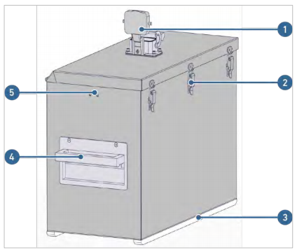
The accumulator is located in an aluminum housing. The lid of the
housing hosts an ODUMac connector which connects the battery with the
electronics.
Batteries have been chosen and are provided by the user which are
easily available on the local market. The trolley requires a supply
voltage of 24 V DC. The batteries used for this trolley are from the
company “energysource”. Two LEDs on top of the battery provide
information on the charging and capacity status. Using light guides and
a plastic interface for the LEDs on the battery, the corresponding
status is visible from the outside of the housing via battery level
indicator.
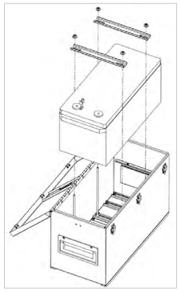
In case the battery has to be exchanged, three quick clamps can easily
be opened to get access to it. The battery is firmly fixed in the
housing by threaded bars and brackets. They can easily be opened.
Batteries with maximum dimensions of 250 x 225 x 500 mm (H x W x D)
are suitable for the housing.
 
Figure 18: Battery housing
Table 4: Batteruy housing
Pos.
|
Description
|
| 1
|
Socket
|
| 2
|
Instep closure
|
| 3
|
Glide bar
|
| 4
|
Latch
|
| 5
|
Battery level indicatorr
|
The following illustrations show the wiring scheme of the battery housing and the ODU-Mac connector:
Figure 19: Wiring scheme battery housing
Figure 20: ODU-MAC connector pin assignment
| ROSEN and IZfP Page 25 of
84 |
Confidential! |
|