HARD SPOT INSPECTION TROLLEY - English -
Page 22/84
Operating and Maintenance Instructions
adaptaed from: https://app.box.com/s/c6qfgtuhfg1yd2ottrfum98x8jmg7rn3
| Hard spot inspection trolley • PLAMAT-M •
18201 |
|
| Operating and
Maintenance Instructions • V2.0 |
Structure and handling of the trolley
|
3.1 Inspection unit
The trolley is equipped with an inspection unit at its front. The unit comprises eight hard spot sensors used for inspecting when in measurement position. The eight sensors are configured in terms of two staggered rows, each with four sensors. This set-up provides full coverage
when scanning the plate.
Holders located at both sides of the unit allow to use chalk for marking purposes. Areas already tested on the plate can thus be marked. Alternatively, an impact rope with chalk can be used to indicated individual lines on the plate.
When rolling the mobile device over uneven ground or slopes (such as ramps), additional wheels at the inspection unit provide support. Depending on the slope, the inspection unit may hit the ramp, even when in parking position. In order to prevent a direct contact between ramp and unit, release the wheels and shift them in lower position. The inspection unit is mounted to the lifting device of the trolley at its rear side.
NOTICE
|
! Potential damage of probes due to uneven ground!
Move the trolley carefully on the ground, in particular at and over uneven areas with significant slopes.
|
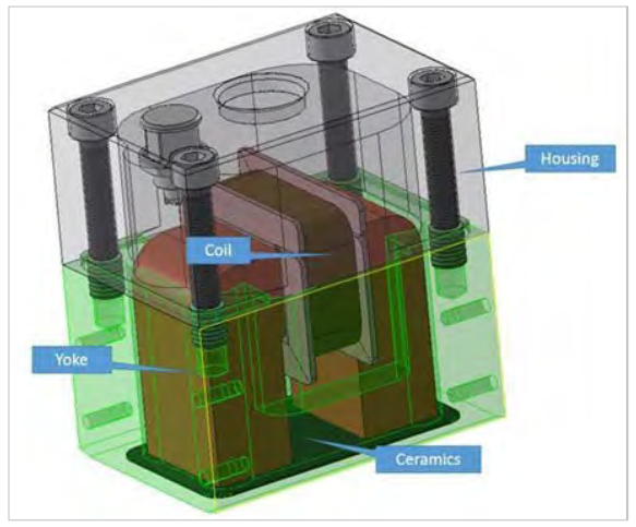 Figure 13: Sensor system in aluminum housing
A ceramic with thickness
0.5 mm is employed between yoke/coil system and the plate. The
ceramic is directly connected to the yoke cross-section, so no
additional lift-off appears. Liftoff is only given by the ceramics
itself and its thickness.
The sensors are not fixed to the frame, they have space to move in vertical direction. The
sensor movement in vertical direction is confined by the springs and the bar above the spring.
Each sensor has an individual clearance and can adapt easily to local conditions on the plate
(such as curvature, dirt, ..). Though the sensors can move in vertical direction, they are
pressed against the plate in a controlled, twofold manner: (1) the springs press each sensor
against the plate and (2) the adhesive magnetic force provides additional normal force.
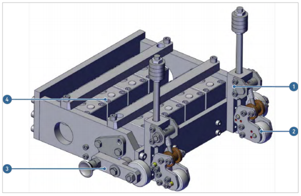
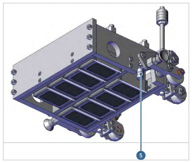
Figure 14: Two views of the Inspection unit
Table 3: Inspection unit
Pos.
|
Description
|
| 1
|
2 x chalk marking unit
|
| 2
|
2 x rollers
|
| 3
|
2 x guide rollers
|
| 4
|
2 x 4 probes
|
| 5
|
1 x inductive proximity
sensor
|
| ROSEN and IZfP Page 22 of
84 |
Confidential! |
|