HARD SPOT INSPECTION TROLLEY - English -
Page 19/84
Operating and Maintenance Instructions
adaptaed from: https://app.box.com/s/c6qfgtuhfg1yd2ottrfum98x8jmg7rn3
| Hard spot inspection trolley • PLAMAT-M •
18201 |
|
| Operating and
Maintenance Instructions • V2.0 |
Fundamental principles
|
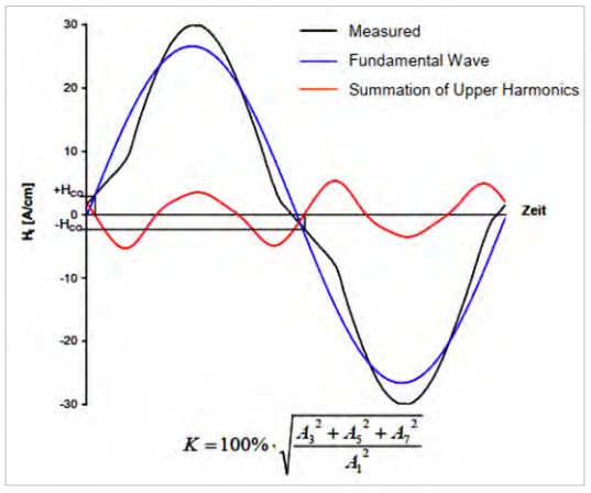
2.5 Upper harmonics
The
generation of the alternating magnetic field in the measuring sample is
carried out by a sinusoidal excitation with the yoke. A closer
inspection of the time signal of the tangential magnetic field in the
sample results in the finding that the curve shape of the measured
field signal is not purely sinusoidal. Especially in the range after
the zero transition distortions are detectable (see Figure 9). The
reason is the non- linear behavior of the ferromagnetic hysteresis. By
Fast Fourier Analysis (FFT) of the measured field a fundamental wave
and the upper harmonic parts can be numerically determined. The upper
harmonic parts give information about the ferromagnetic properties of
the tested material.
Figure 9: Harmonic distortion
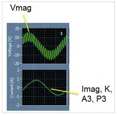
The following micro-magnetic parameters are considered for the upper harmonics analysis:
| Vmag [V] |
amplitude of magnetization voltage |
| Imag [A] |
amplitude of magnetization current |
| K [%] |
Klirr factor of magnetization current |
| A3 [%] |
3rd harmonics amplitude of magnetization current |
| P3 [rad] |
3rd harmonics phase of magnetization current |
Figure 10: Visualization of harmonic distortion
| ROSEN and IZfP Page 19 of
84 |
Confidential! |
|