HARD SPOT INSPECTION TROLLEY - English -
Page 16/84
Operating and Maintenance Instructions
adaptaed from: https://app.box.com/s/c6qfgtuhfg1yd2ottrfum98x8jmg7rn3
| Hard spot inspection trolley • PLAMAT-M •
18201 |
|
| Operating and
Maintenance Instructions • V2.0 |
Fundamental principles
|
2.3 Eddy current
The EC testing method is based on the approach of generating electrical currents in
conductive materials, here the pipe wall. The figure below summarizes the principle. An
alternating electric current with defined amplitude and frequency is applied to a coil system.
The driving current generates an alternating primary magnetic field which causes eddy
currents to flow in the surface of the nearby pipe wall by mutual inductance. The currents in
the pipe wall produce a secondary magnetic field which is opposed to the primary field
inducing it. Defect damage such as corrosion leads to a change of the EC’s flow direction,
which influences the mutual inductance. This can be described by a variation in the electrical
impedance of the coil, i.e., its Ohmic resistance and inductive reactance.
The impedance is usually measured across a bridge circuit in which any imbalance can be
measured accurately. On the basis of this imbalance, material inhomogeneities can be
detected and their properties determined by the evaluation of the amplitude and the phase
shift between the input and output signals.
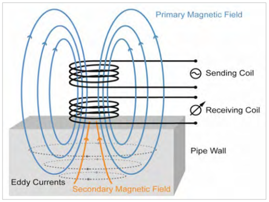
Figure 4: The EC principle
In
addition to material properties such as the electric conductivity and
magnetic permeability, the frequency of the input signal also
determines the so-called skin depth of eddy currents.
The skin depth is a measurement of the distance to which an alternating
current can effectively penetrate beneath the surface of a conductive
material, in this case the pipe wall.
For suitable frequencies and standard steel grades the skin depth for
carbon steel is well below 1 mm. Thus, the EC approach can be
considered to be a surface-sensitive method.
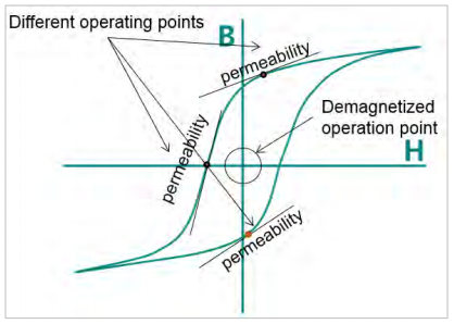
The magnetic permeability generally depends on the operating point of magnetization, which usually comprises:
- demagnetized operation point
- residual magnetized operating point
Figure 5: Magnetic hysteresis loop and operating points
Since the EC approach considered here is surface- bonded, surface
influences may have and disturbing character, e.g. tinder, roughness,
etc.
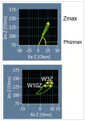
The following micro-magnetic parameters are considered for the EC analysis:
| Zmax [Ohm] |
maximum magnitude of the impedance |
| Zmin [Ohm] |
minimum magnitude of the impedance |
| Zmean [Ohm] |
averaged magnitude of the impedance |
| Phizmax [rad] |
maximum phase of the impedance |
| Phizmin [rad] |
minimum phase of the impedance |
| Phizmean [rad] |
averaged phase of the impedance |
| W3Z [Ohm] |
3 % widening of the eddy current loop |
| W10Z [Ohm] |
10 % widening of the eddy current loop |
Figure 6: EC impedance plane
| ROSEN and IZfP Page 16 of
84 |
Confidential! |
|